


The OPB9000 is a reflective light
sensor from TTElectronics with programmable output and sensitivity
levels. Let's take a look at its design and hook it up to an
oscilloscope for some insight on how that design functions in real time.
We'll also talk about Manchester-encoded data.
With a footprint of only 4mm x 2.2mm, this sensor can be incorporated into almost any PCB or used off-board with a 4-wire harness (Gnd, Vcc, cal/status, and output). Only two wires (cal/status and output) need to be connected to a host microcontroller for calibration and, once calibrated, only one wire is required to read the state of the sensor.
This non-contact sensor can be incorporated into printers to detect the edge of a paper, or act as a limit-switch in an actuator. In hospitals, this device can alert nurses if a bubble has entered an IV tube or if an IV bag has emptied. Additional applications include tamper-detection, automatic dispensing, and any other application where a single-pole single-throw (SPST) switch might be replaced with this non-contact presence detector.
AAC was provided the Photologic V OPB9000 reflective sensor evaluation kit for use in this article.
About the Device
This sensor functions with eight small pads. Two signal pins (OUT, CAL/STATUS) communicate data to and from a host microcontroller via Manchester-encoded data streams. Two ground pins (GND, DGND) provide analog and digital ground references. Power comes into the device via Vdd, and externally connects to the LED anode. The LED cathode externally connects to the LED I-SINK pin; this arrangement allows an external LED to be used, if needed.An internal EEPROM stores the sensitivity settings, LED intensity settings, and output type—once calibrated, the device will return to these settings at the next power-on. The output signal can be configured to respond to either increasing or decreasing signal levels.

OPB9000 block diagram from datasheet
Manchester-Encoded Data
Manchester encoding allows a transmitter to incorporate synchronization information into a digital data stream. In its simplest implementation, a clock signal is XORed with a data signal to produce the Manchester-encoded output. Check out our article on Manchester encoding for more information.
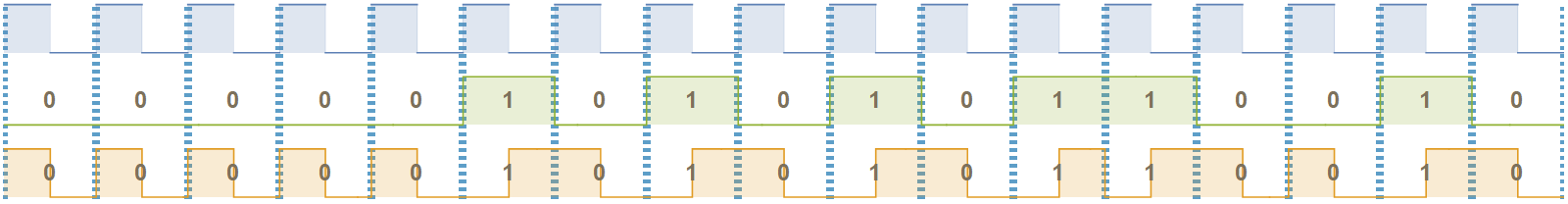
Clock (blue) and data (green) combine to create Manchester-encoded data (orange)
The OPB9000 uses IEEE standard 802.3, where 0 is a high-to-low transmission and 1 is a low-to-high transmission. This communication standard allows engineers to minimize the number of wires required to connect to a host microcontroller as well as to more easily provide galvanic isolation if a design requires it. According to TTElectronics engineers I spoke to, “Many applications...utilize upwards of 20 or so of these sensors, sometimes over 30, so every wire” increases the overall cost. The “next generation sensor will no longer [use] Manchester, it [will] be I2C or similar, to improve the compatibility with most microcontrollers.”

Manchester-encoded data generated by the sensor, measured with a Tektronix MDO3104 oscilloscope.
Commands are sent to the OPB9000 via the calibration/status (CAL/STAT) pin. Data is read from the device via the output pin. When not transmitting data, the output pin indicates whether or not an object has been detected.
Experimenting with the Device
The OPB9000 is described as being able to detect a very small change in reflectivity. I wanted to test this with substances that have relatively similar refractive indices—I chose water in a polyvinyl chloride tube ()—this is similar to the use case of detecting saline in intravenous (IV) tubing.
The datasheet indicates that the minimum recommended operating distance is 2.5mm, so I placed the tube in a piece of acrylic. The wall thickness of the acrylic plus the wall thickness of the tube provided an approximate separation of water-surface-to-sensor of approximately 0.10” (2.54 mm). I notched out the acrylic to prevent interference in the experiment.

Experiment setup shows the OPB9000 sensor attached to an acrylic tube that contains a piece of PVC tubing. A syringe is used to control the water level inside the tube near the sensor.

Side view of the experimental setup (not to scale) shows water (gray) inside a clear PVC tube held inside a piece of acrylic. The OPB9000 is temporarily affixed to the tube with UV-cure glue.
A first-order approximation is given by
. Traveling from the sensor through the air to the PVC tube, approximately 4.5% of the LED light is reflected
The actual amount of reflected light is a tad different from these estimates (due to reflection off the back wall of the tube, refraction through water, and lensing effects caused by the cylindrical shape of the water and tube).
I was not entirely certain that the OPB9000 would be able to detect water in the tube without carefully setting the sensitivity and LED intensity in a controlled environment but it worked out of the box. I only had to run the built-in calibration sequence.
See the video below to watch the experiment.
There is one caveat—the sensor turned on immediately as the water level rose, but it did not turn off immediately when the water level fell. That is because as the water level drops, a thin film of water is held along the inside wall of the tube by adhesive forces between the water molecules and the PVC. That thin film has a different effective viscosity than the main volume of water and takes a certain amount of time to travel down the tube under the influence of gravity.
Since reflection happens at the interface of two mediums, the sensor detects the presence of the water/PVC interface, not the amount of water present.
Conclusion
The OPB9000 is a very small non-contact reflective sensor that can fit on almost any circuit board. Multiple sensors can be used to provide gesture detection, and single sensors can take the place of almost any contact or non-contact limit switch.


No comments:
Post a Comment