


This article outlines traditional
half-duplex RS-485 configurations and then presents new alternatives for
simplifying the control interface by eliminating the required control
lines and software control code.

Figure 1. DIN Connector
One of the challenges for networks that have multiple RS-485 transceivers is to manage the local receive and transmit enable pins. For true multi-channel, bi-directional transmission, these pins provide a means for system designers to determine when the RS-485 is transmitting or receiving. Depending on the application, these two enable pins can be connected to each other through PCB traces to a local processor or controller. With this type of connection, there are three lines to isolate: the driver and receiver enable (DE/RE), the driver input (DI), and the receiver output (RO) lines.
Traditional Half-Duplex RS485 Configurations
RS-485 (TIA/EIA-485) is a wired communication standard that uses differential signals to allow data transmissions over long distances. In noisy industrial and factory automation environments, the RS-485 differential signals make it more robust and withstand common-mode noise. The twisted-pair signal cable ensures that received interference is mostly common mode.Bidirectional channels use half-duplex devices for communication over a pair of twisted cable. For the RS-485 device, the Rx and Tx terminals connect to the A (noninverting) and B (inverting) IC package pins. The receiver’s output (RO) and the driver’s input (DI) terminals connect to separate pins (Figure 2).
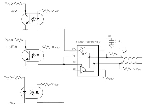
Figure 2. An isolated half-duplex RS-485 channel contains three or four optocouplers to accomplish full signal transceiver activity.
In certain applications, isolation from optocouplers or other isolators is required. The optocoupler channels in Figure 2 clearly illustrate the number of required lines for the RS-485 transceiver. Note the connection of the RE and DE pins. In most applications, this connection is appropriate. In other applications, the RE and DE pins are separate. The system processor or controller drives the RE and DE control pins in response to the length of time that a node must stay enabled for transmitted packets of data, which vary from application to application.
Removing Control Lines in an RS-485 Network
The MAX13487E successfully eliminates the manipulation of the RS-485 transceiver’s RE and DE control lines by using an on-chip AutoDirection state machine (Figure 3).
Figure 3. A functional diagram of the MAX13487E (a reduced slew-rate driver) and the MAX12488E (an unlimited slew-rate driver).
In Figure 3, the proper AutoDirection state machine configuration is to connect the RE and SHDN pins high and for proper operation use an external pull-up resistor on A and a pull-down resistor on B.
Although signal isolation is not a requirement, the optocoupler channels in Figure 4 clearly illustrate the number of required lines for the RS-485 transceiver.

Figure 4. A half-duplex MAX13487E, RS-485 transceiver with an internal AutoDirection stage machine reduces the isolation channel count from three or four to two.
In Figure 4, the MAX13487E’s active digital channels are the DI (transmit) and RO (receive) pins. The AutoDirection state machine determines whether the device or another node on the network is driving the bus. Depending on the activity on the bus, the AutoDirection state machine automatically disables or enables the MAX13487E driver and receiver.
A conventional RS-485 transceiver uses DE and RE inputs for driver and receiver enable/disable states. In contrast, the MAX13487E/MAX13488E internal state machine, which enables and disables the driver, substitutes for the absence of the DE input. For proper operation, the non-transmitting MAX13487E/MAX13488E requires a high DI input, keeping the device in its idle state.
In this manner, the MAX13487E AutoDirection state machine facilitates the transmission and reception of active signals on the RS-485 bus as well as changes to a high-impedance mode by monitoring the RS-485’s driver and bus activity.
The MAX13487E/MAX13488E are half-duplex RS-485/RS-422-compatible transceivers with AutoDirection control. The MAX13487E, which is appropriate for this optocoupler application, has reduced slew-rate drivers that minimize EMI and reduce reflections caused by improperly terminated cables, allowing error-free transmission up to 500kbps. There are no slew-rate limits for the MAX13488E, enabling transmit speeds up to 16Mbps.
Conclusion
The MAX13487E/MAX13488E RS-485 transceivers provide a half-duplex interface solution. The MAX13487E/MAX13488E on-chip AutoDirection state machine effortlessly manages the RS-485 half-duplex receiver and transmission tasks while using only one control line. This design solution explained how the MAX13487E reduces slew-rate drive to minimize EMI and reduce reflections. The AutoDirection circuitry tackles this interface problem while also simplifying the circuit by eliminating the need for the dedicated microcontroller/processor control pins and the PCB lines.


No comments:
Post a Comment