


Learn about the basics of grounds, grounding, and ground symbols. Not all grounds are created equal. In this article, we'll discuss earth ground, common ground, analog ground, and digital ground.
What is ground?
In electronics and electrical engineering, it is by convention we define a point in a circuit as a reference point. This reference point is known as ground (or GND) and carries a voltage of 0V. Voltage measurements are relative measurements. That is, a voltage measurement must be compared to another point in the circuit. If it is not, the measurement is meaningless.The ground reference point is often, but not always—more on this later—represented by a standard ground symbol. See Figure 1.

Figure 1. Common ground symbol.
Typically, this reference point is the base for all other voltage measurements within the circuit. However, not all voltage measurements are taken from this reference point. For instance, if you were to measure the voltage across the upper resistor in a resistive voltage divider, your reference point would not be ground. See Figure 2.
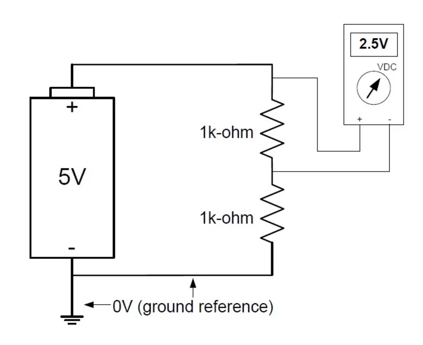
Figure 2. Not all voltage measurements are in reference to ground.
Earth Ground
Earth ground is exactly as it sounds. It's a ground physically (and electrically) connected to earth via a conductive material such as copper, aluminum, or an aluminum alloy.A true earth ground, as defined by the National Electrical Code (NEC), consists of a conductive pipe, or rod, physically driven into the earth to a minimum depth of 8 feet.
The earth provides an electrically neutral body, and due to the earth's virtually infinite state of neutrality, it is immune to electrical wavering. Power poles, those that are strung throughout neighborhoods, are also connected to ground. Figure 3 shows an earth grounding wire attached to a power pole.

Figure 3. Power poles have earth grounding wires connected to them.

Figure 4. The third prong 110VAC outlet.
This outlet connection to earth ground provides a means for, as an example, test equipment to be connected to earth ground—the ground (green) wire from a power cord is connected to the equipment's internal frame or chassis. And when connecting various pieces of test equipment to earth ground, they are all connected to a common grounding point, and, therefore, have a common reference. You can verify this point by measuring the resistance between the ground terminals of any two pieces of test equipment.
This common reference is brought out, to the user, as a ground lead terminal. Side note: your desktop computer's chassis is also connected to earth ground.

Figure 5. Test Equipment provides the user with earth ground lead terminals. Original image courtesy of cal-center.us. Note added by author.
The earth ground symbol is, unfortunately, used in many applications in electronics and electrical engineering, often meaning different things to different people, so it may be a bit confusing to some beginners. For instance, the earth ground symbol is also used as a common ground symbol or a 0V reference. This is a bit misleading because a 0V reference is not actually connected to earth ground. Figure 6 shows various ground connections using the common/earth ground symbol.
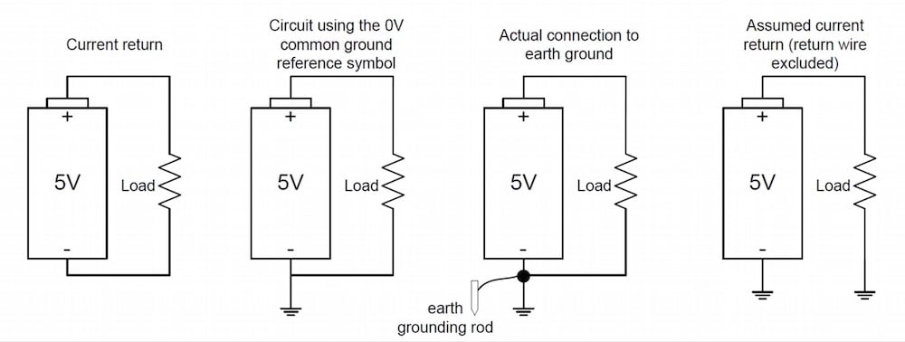
Figure 6. Various ground connections using the earth ground symbol.
Analog and Digital Grounds
Digital circuits generate spikes of current when the digital signals change states. When load currents change in analog circuits, current spikes are generated again.Although there are multiple techniques for proper grounding, when it comes to mixed-signal grounding it's of most importance—regardless of which grounding technique is adopted—to separate the "more-noisy" digital return currents from the "less-noisy" analog return currents. This separation of the grounds helps to minimize or prevent noise from being generated within circuits due to ground currents.
Such ground currents—think of them as changing currents—when applied to ground return paths, create voltage variations (recall Ohm's Law) called noise. You may have heard the term "a noisy ground." Such noise can compromise sensitive signals in local circuits. Grounding has always been a major obstacle for design, system, and test engineers.
One possible grounding technique, which can be helpful in some, but not all, situations, uses what is called a "star" ground. This philosophy builds on the theory that all voltages in a circuit are referred to a single ground point.
Figure 7 depicts a single grounding point connection for both analog and digital grounds.

Figure 7. A single point grounding for digital and analog grounds.
The method of using single grounding points (or star grounds) looks great on paper. In practice, however, it can be very difficult to implement depending on the complexity of one's design. An alternative approach is to use a grounded bus bar.
Keep in mind, though, that physically separating analog and digital grounds is generally not required because return currents can be managed via proper PCB layout even when the design uses a single (shared) ground plane.
Common Grounding Error
A three-terminal DC power supply, such as the one in Figure 8, may be a little confusing to beginners. This power supply has a positive (+), a negative (-), and a GND (ground) terminal. As mentioned previously, the ground terminal (earth ground) is physically tied to the chassis, which in turn is connected to the ground wire within the power cord, which is finally connected to the earth via the three prong outlet.A fairly common mistake made by beginners is to connect a load between the positive (+) and the GND terminals. This incorrect connection won't allow the current to return to its energy source (the power supply itself), and, therefore, no current will flow. The proper connection is to connect the load between the positive (+) and negative (-) terminals.

Figure 8. DC power supply with earth ground connection (green terminal in the center). Image courtesy of GWInstek.com.
Electrostatic Discharge (ESD)
The grounding of your test equipment also helps in the elimination of electrostatic discharge (ESD). ESD occurs when a statically-charged body (i.e., you) comes in contact with the test equipment. Some test equipment is ultra sensitive and may be very vulnerable to ESD events.Integrated circuits (ICs) are notorious for being ultra vulnerable to ESD events. Grounded mats (referred to as ESD mats), grounded chairs, and wrist straps provide adequate ESD protection for your ICs by grounding you—thus discharging any static you may have on your body—prior to touching any sensitive components. Most engineers and technicians also wear ESD-safe jackets when working with PCBs and ICs for added protection against possibly damaging components and equipment.
Ground Symbols
The following ground symbols are some that may be found in designs: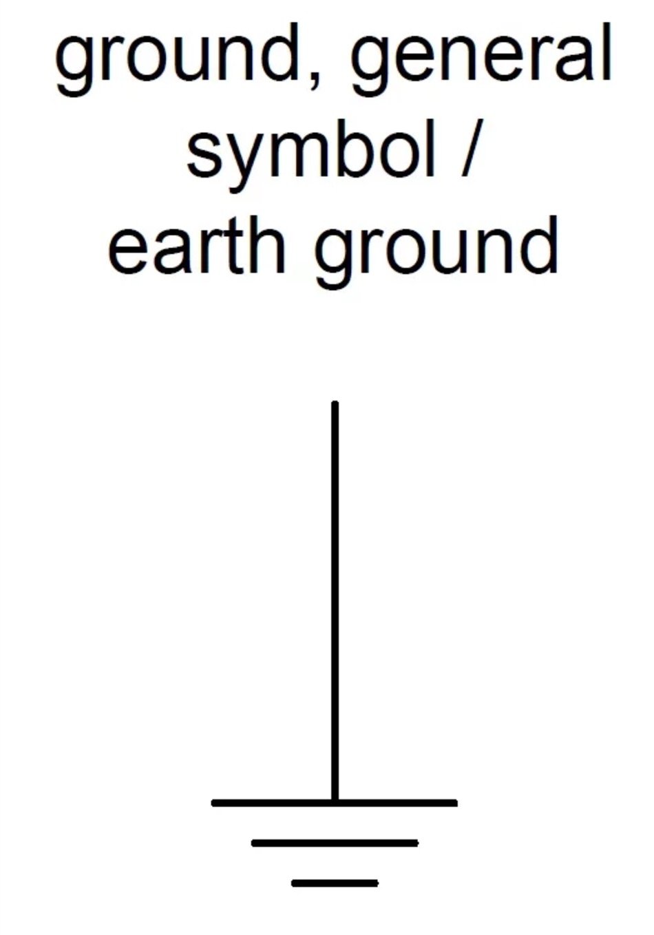
Figure 9. General ground symbol, or earth ground (IEEE Std 315-1975 section 3.9.1 and IEC 60417-5017).
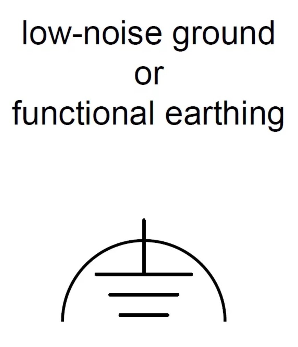
Figure 10. Low-noise ground, or functional earthing (IEEE Std 315-1975 section 3.9.1.1 and IEC 60417-5018).

Figure 11. Safety or protective ground (IEEE Std 315-1975 section 3.9.1.2 and IEC 60417-5019).

Figure 12. Chassis or frame connection (IEEE Std 315-1975 section 3.9.2 and IEC 60417-5020).


No comments:
Post a Comment