


Harmonic distortion can be
introduced to audio amplifiers from many sources. Fortunately, reducing
this distortion involves following proven design practice, and if
careful enough attention is paid to the design, total harmonic
distortion can even be reduced to levels below the threshold of human
hearing.
In my previous article on harmonics and THD in audio systems,
I explained that in the world of audiophiles there are subjectivists
and rationalists. Subjectivists are people who believe that amplifiers
should be allowed to shape (i.e., distort) the sound so that it sounds
the best. Rationalists are people who believe that an audio system
should faithfully reproduce the original recording without adding any
type of distortion.I admitted that I am not able to resolve the debate between subjectivists and rationalists, but that as an engineer I tend to side with the rationalists. As engineers, we like to be able to test and measure and quantify aspects of systems and signals, but there is no measurement that quantifies what sounds best. We can, however, quantify aspects of an audio system that change the nature of the input signal, and these things include total harmonic distortion (THD), phase delay, intermodulation distortion, and noise.
From the point of view of the rationalists, since we can objectively measure these things, we can use these measurements to identify what audio system changes the input signal the least.
In this article, I want to focus on total harmonic distortion and identify the main causes of THD in the classic three-stage audio amplifier (see Figure 1), and I'll also describe how that THD can be reduced.

Figure 1. Heavily simplified model of a three-stage audio power amplifier
Power Audio Specifications
Before getting into the specifics of THD in audio amplifiers, let’s consider the difference between regulations/standards for power systems and regulations/standards for audio systems. To start with, standards in power systems are probably more important because the THD produced by power systems and power electronics can affect the power grid and everyone connected to the power grid. THD produced by audio systems mostly just has an effect on the eardrums of the listeners. At the same time, regulations for power systems are also easier to define because there is only one fundamental frequency—the line frequency that THD needs to be measured against. Some of the standards for THD and power factor of power systems and power electronics are discussed in another of my previous articles on THD in power systems.Audio systems, on the other hand, work over a range of frequencies, the audio range, which is about 20 Hertz up to 20 kHz. So to get a full idea of the THD, a number of frequencies in that range need to be tested, and that means one THD number does not tell the whole story. Typically though, one THD number is used and it represents the THD at one particular frequency, but that doesn’t mean the THD at other frequencies will be the same. Human perception complicates things even further. The way humans perceive harmonics also means that one THD reading does not fully capture the effect of THD on the listening experience, since human hearing is more sensitive to some frequencies than to others. Despite these measurement difficulties, standards in audio systems do exist, but ones like the FTC amplifier rule simply describe what information needs to be stated (without providing guidance on how the measurements should be taken), and ones like THX certification are completely voluntary.
These challenges do not mean THD measurements are useless or that there is little point in making comparisons between devices. It does mean that you should be wary of what the specifications of an amplifier are actually telling you. For example, these three THD specifications are all for audio amplifiers, but it is impossible to make a comparison between them:
- 0.1% THD at 1kHz
- 0.08% THD into 8 ohm speakers
- 0.15% THD+N at 1kHz at rated power into 8 ohm speakers, 22kHz bandwidth
None of these examples give information in a format for meaningful comparison, and the first two examples do not give enough information at all. What is the power output at which those were tested, and what is the bandwidth that was tested? The third example gives a THD+N measurement, which can’t be compared to straight THD measurements. THD+N is THD plus noise; it's a common measurement in audio systems, but if one system uses THD and one uses THD+N, how do you compare the two?
Another example of where THD is indirectly part of an amplifier specification is maximum power output. The maximum power output is the output power achievable when you allow up to a certain amount of distortion. If you allow for a higher distortion, you can get a higher maximum output power, so it can be advantageous to allow for that higher distortion. Typically this power measurement is done when THD is at 1%, but it is also commonly measured at THD of 10%. It is very important when making comparisons between amplifiers that you know which THD level is being used.
Now that we have considered the difficulty of comparing THD produced by different amplifiers, let’s approach this problem from a different angle and look into how to design a system with a minimal amount of THD.
Sources of Undesired THD
Renowned audio specialist Douglas Self identifies 8 sources of distortion for three-stage solid-state audio power amplifiers [1]: input pair differences, nonlinearities in the voltage amplifier stage (VAS), output stage distortion, loading of the voltage amplifier stage, rail decoupling distortion, induction distortion, negative feedback distortion, and capacitor distortion. This section briefly describes each source and provides some hints about how distortion can be reduced from each source.Input Pair Differences
The input stage of the classic three-stage amplifier consists of a differential pair of transistors. When there is a mismatch between the characteristics of the transistors or the DC biasing is not matched, distortion will occur. Even with good matching, distortion at higher frequencies shows up due to capacitances looking more like short circuits at higher frequencies; this reduced impedance leads to higher current.Nonlinearities in Voltage Amplifier Stage
The voltage amplifier stage is a common-emitter configuration. Linear models are used for small-signal analysis of the common emitter configuration, but the transistor, in fact, behaves nonlinearly. This nonlinearity contributes to harmonic distortion, but large open-loop gain along with the use of a negative feedback loop will mostly eliminate this source of distortion.Output Stage Distortion
The output stage is usually a Class B push-pull type of amplifier. The main distortion contribution of this stage is crossover distortion, and this type of distortion will be discussed later.VAS Loading Distortion
The input impedance of the output stage is nonlinear. Since this impedance is the load of the voltage amplifier stage, the VAS output gets distorted. Buffering between the voltage amplifier and output stage reduces this distortion.Rail Decoupling Distortion
Decoupling capacitors on the power rails are always a necessity, but if the current return path (i.e., ground) of these capacitors is shared with the input or feedback circuitry, then the harmonic content of the power supply rails will be introduced to the signal. This type of distortion has an easy fix of keeping the current return path of the decoupling capacitors separate.Induction Distortion
This type of distortion is caused by an inductive effect between the DC supply and the input and feedback paths. It can be minimized by reducing the ways the supply and input/feedback paths can interfere with each other, i.e., keeping the loop area of the input and feedback signals as small as possible and physically separating the supply and input/feedback circuitry as much as possible.Negative Feedback Distortion
The output signal and the point where the same signal is fed back to the negative feedback path are theoretically the same, but since wire/track resistance is finite, the signals may not actually be the same. Ensuring that feedback is taken from the correct point in the circuit will eliminate this distortion.Capacitor Distortion
When used for coupling or DC blocking, electrolytic capacitors tend to distort signals when the AC voltage across them is high. Ceramic capacitors can also be problematic because they have a significant non-linear change in capacitance over frequency. When the frequency of the audio signal changes, so does the capacitance. Ceramics can also pick up mechanical vibrations and convert them into electrical noise (this is a piezoelectric effect). In audio applications, film capacitors are the best choice for AC coupling and DC blocking capacitors. Electrolytics can still be used for DC filtering, but ceramic capacitors should be avoided.Output (Crossover) Distortion
These sources of distortion, except output distortion, are easy to eliminate using clever but straightforward-to-implement circuit design techniques. Considering these sources of distortion and the means to reduce them, Douglas Self developed the concept of the blameless amplifier. A blameless amplifier is one that is not perfect, but has all easily addressed distortion mechanisms minimized.A blameless amplifier is therefore left with output distortion (which is mostly crossover distortion), the most difficult source of distortion to eliminate. Crossover distortion is probably the most well-discussed source of THD in audio systems for the very reason that it is not easy to eliminate. Crossover distortion occurs because in a class B amplifier there is a short period when both output transistors are biased off. During this time there is no output signal. The scope captures below show an example of the crossover distortion of a class B amplifier in both the time domain and frequency domain. It is quite clear that the output signal is distorted from the input signal and that there are significant harmonics in that signal.

Figure 2. Crossover distortion in the time and frequency domains.
For more information about the quantity of THD in a signal like this, this article goes through the process of calculating the THD in a signal with crossover distortion.
Proper biasing techniques can significantly reduce (but not eliminate) the amount of crossover distortion. To eliminate crossover distortion would involve pushing the amplifiers into class AB mode. A simple system modification to bias the bases of the output transistors using diodes is an easy way to reduce crossover distortion. Figure 3 shows a basic class B amplifier with diodes between the bases to bias the output transistors closer to their turn-on point. This biasing method assumes that the forward-bias voltage of the two diodes is slightly lower than the base-emitter turn-on voltages of the two transistors. If the forward-bias voltage of the diodes were higher than the base-emitter turn-on voltages, this amplifier would no longer be class B, it would be class AB. This method is not the only biasing method that can be used. Other common methods are to use diode-connected BJTs and rubber diodes.
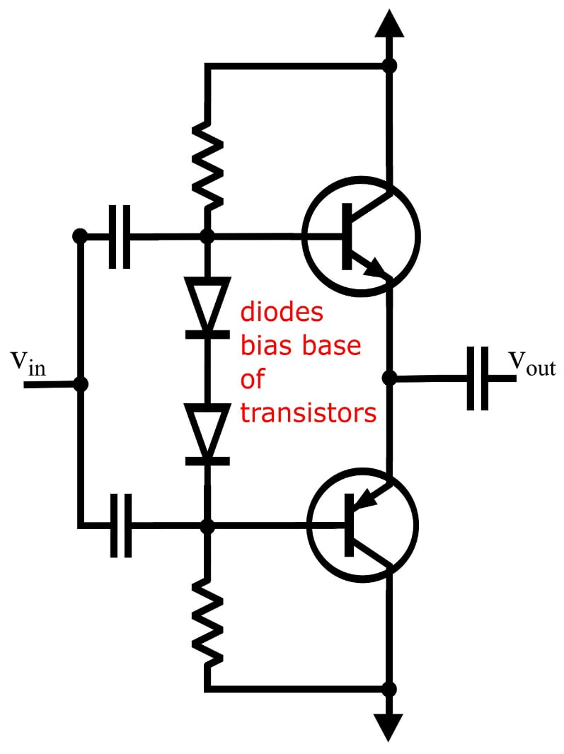
Figure 3. Biasing output transistors with diodes to reduce crossover distortion.
The result of this biasing is that the crossover distortion is significantly reduced, as can be seen in Figures 4 and 5. The oscilloscope image on the left of Figure 4 compares the input (yellow) to the output (blue), and the image on the right shows the small amount of distortion at the zero-crossing point.

Figure 4. Time domain view of reduced crossover distortion.

Figure 5. Frequency domain view of reduced crossover distortion.
While this biasing does not eliminate the crossover distortion, it is certainly reduced. Is it reduced enough? Well, that depends on what you are looking for in a system and how much THD you can handle. This level of THD is probably perceptible, but will it affect your listening experience? And if it does affect your listening experience, would you pay more for a system with lower THD? While the measurements of THD are certainly not subjective, in the end, your choice of audio system is a subjective one, even if you are not a subjectivist.
Final Words
This article has addressed harmonic distortion in audio amplifier systems based on the classic three-stage configuration (see Figure 1). Most of the sources of distortion can be reduced below perceptible levels by means of careful design practices. Even output distortion can be significantly reduced, and if you are willing to pay for it, it can even be reduced below the level of perception.Reference
[1] D. Self, Audio power amplifier design handbook, 4th ed. Newnes, 2006.


No comments:
Post a Comment