


Pendulum is one apparatus which is
weightless, stiff bar that experiences no friction, and can swing
freely. Pendulum can move to and fro from its equilibrium position,
depending on restoring the force due to the gravity and can accelerate
back to its equilibrium position. Pendulum is not only used in clocks it
can also be used in seismometers. During Middle Ages pendulums were
used for torturing victims wherein pendulum bobs were replaced by axe
and rotated in to and fro motion until the demise of the victim.
This article discusses the operation of the pendulum implemented by using basic 8051 microcontroller. The bob motion is indicated with the use of LED lights
and its frequency of turning on and off is decided by the
microcontroller. A brief description about the pendulum circuit and its
operation is given below.
8051 Microcontroller Based Pendulum Operation
Nowadays many of us are buying different
types of wall clocks available in the market. These clocks produce
sound, but are quite expensive. The circuit described here produces
sound which means time is indicated with the help of LEDs. In this
circuit, the LEDs are arranged in such a way that you will get time in
the form of a pendulum in one direction and then moves in opposite
direction.
Circuit Description:
The circuit is based on an 8051 microcontroller and a few other components such as crystal oscillator, capacitor reset circuit, capacitors, resistors and LEDs. The 8051 microcontroller is most popular microcontroller as many of the projects
are done by using this microcontroller. An 8-bit microcontroller is
used to control all the operations. It controls all the LEDs through
ports.
This project employs multi-pattern
running lights for generating several designs of running lights.
Moreover, LEDs are used for display. The design of the LEDs can be
selected by moving up and down. A Microcontroller is used for
continuously monitoring the switches, and the switching off the LEDs is
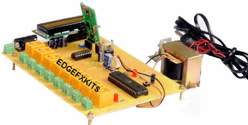
done in accordance with the embedded C programming done in the microcontroller by using KEIL software. The power for the entire circuit is derived from a step down transformer, and a voltage regulator is used in the power supply circuit. The voltage regulator produces a constant output of 5V.
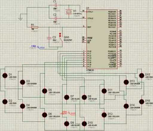
Circuit Diagram
Components
Resistors: Resistors
are passive components used to control the current in circuit.
Resistance is defined as the ratio of voltage applied across its
terminals to the current passing through it. The value of resistor
depends on a fixed voltage that limits the current through it.
Capacitors: Capacitor
is a component used for storing charge. The charge stored in the
capacitor is defined as the product of its capacitance value and the
voltage applied across it.
Crystal Oscillator: Crystal oscillator circuit is an electronic circuit
that makes use of the mechanical resonance of a vibrating circuit to
generate an electrical signal with respect to the frequency. An 8051
operates the crystals for synchronizing its operation. The kind of
synchronization made is known as machine cycle.
Reset Circuit: Reset is
used to set the primary values of an 8051 microcontroller. This reset
circuit purpose is to set the elevation of two machine rotations.
8051 Microcontroller:
This microcontroller consists of 40 pins dependent on the Harvard
architecture in which the program memory and data memory are entirely
different. This microcontroller can be used in a wide range of systems
because it can be easily integrated in any project.
LEDs: Light emitting diodes
are semiconductor light sources. The light emitted from the LEDs varies
between visible to Infra red and ultra violet region. This diode
operates at low voltage and power. LEDs are one of the most common
electronic components used for indication purpose in circuits.
Circuit Operation
- In this system, a crystal oscillator is connected between the pins 18 and 19 of the microcontroller used for operating the set of instructions at a certain clock frequency. A machine cycle is used to measure the minimum time during the execution of a single instruction set.
- Reset circuit is connected to the pin 9 of the microcontroller with the use of a capacitor and resistor. The resistor and capacitor are connected in such a way that they perform a manual reset mode of operation. If the switch is closed, then the reset pin is set high.
- There are eight sets of LEDs, and each set of LED is connected to each pin in the port 1 of the microcontroller. The other ends of the LEDs are connected to the ground. The remaining sets of LEDs are also connected to the remaining pins in the port 1 of the microcontroller and the other end is connected to the ground.
- Each set of the LEDs is switched for particular time duration as with the case of a pendulum in which the microcontroller is programmed in KEIL software.
- When the power supply is given to the circuit, the LEDs glow in a pendulum like fashion i.e.,from left to right and then from right to left with the time period set in the microcontroller program. We can also reset the output display by pressing the reset button.
Thus, this microcontroller based project
describes about the design of a pendulum, and its operation is
displayed by using a set of LED lights. You can also get some more 8051
microcontroller based projects from the list given below:
Microcontroller 8051 Based Mini Projects
8051 Projects
Earlier we have published different
project ideas such as ECE mini projects; microcontroller based mini
project ideas, and so on. All those project ideas were collected from
different sources owing to their helpfulness for engineering students.
Moreover, this particular article also mentions some latest microcontroller 8051 based mini projects. These 8051 projects are very useful for the engineering students pursuing III and IV year.
- 8051 Microcontroller Based Automatic Parking Slot Indicator
- RFID based Time Attendance System and Access Controlling Using Microcontroller
- Microcontroller based automatic bell System for Institutions and Schools
- Color Sensing Interfacing with Different Wavelengths to Microcontroller
- Password Based Digital Locking System with 8051 Microcontroller
- Bio medical heart beat monitoring using 8051 Microcontroller
- 8051 Microcontroller Based Seven Segment Multiplexing
- Water Level Monitoring and Controlling System Using 8051 Microcontroller
- Parallel Telephone with Auto Secrecy Using 8051 Microcontroller
- 8051 Microcontroller Based Non Contact Digital Tachometer
- Standalone Temperature Measuring System Using Microcontroller
- Color Sensing Interfacing with Different Wavelengths to Microcontroller
- GSM based Patient Monitoring System with 8051 Microcontroller
- Digital Card Dash Board with Data Recording Capability Using8051 Microcontroller
- 8 Candidate Quiz Buzzer Circuit by Using 8051 Microcontroller.
Therefore, the above mentioned 8051
microcontroller based project for observing the pendulum operation
providesclear explanationwith simple circuit connections. You might have
followed the given list of projects for your further application based
ideas, and therefore, you can comment below for any technical help to
implement these projects.


No comments:
Post a Comment