


In this modern era of wireless communication,
many engineers are showing interest to do specialization in
communication fields, but this requires basic knowledge of fundamental
communication concepts such as types of antennas, electromagnetic
radiation and various phenomena related to propagation, etc. In case of
wireless communication systems, antennas play a prominent role as they
convert the electronic signals into electromagnetic waves efficiently.
Types of Antennas
Antennas are basic components of any electrical circuit
as they provide interconnecting links between transmitter and free
space or between free space and receiver. Before we discuss about
antenna types, there are a few properties that need to be understood.
Apart from these properties, we also cover about different types of
antennas used in communication system in detail.
Properties of Antennas
- Antenna Gain
- Aperture
- Directivity and bandwidth
- Polarization
- Effective length
- Polar diagram
Antenna Gain: The
parameter that measures the degree of directivity of antenna’s radial
pattern is known as gain. An antenna with a higher gain is more
effective in its radiation pattern. Antennas are designed in such a way
that power raises in wanted direction and decreases in unwanted
directions.
G = (power radiated by an antenna)/(power radiated by refernce antenna)
Aperture: This aperture
is also known as the effective aperture of the antenna that actively
participate in transmission and reception of electromagnetic waves. The
power received by the antenna gets associated with collective area. This
collected area of an antenna is known as effective aperture.
Pr = Pd*A watts
A=pr/ pd m2
A=pr/ pd m2
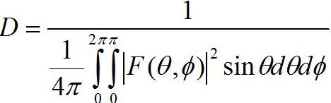
Directivity and Bandwidth:
The directive of an antenna is defined as the measure of concentrated
power radiation in a particular direction. It may be considered as the
capability of an antenna to direct radiated power in a given direction.
It can also be noted as the ratio of the radiation intensity in a given
direction to the average radiation intensity. Bandwidth is one of the
desired parameters to choose an antenna. It can be defined as the range
of frequencies over which an antenna can properly radiates energy and
receives energy.
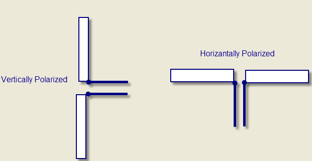
Polarization: An
electromagnetic wave launched from an antenna may be polarized
vertically and horizontally. If the wave gets polarized in the vertical
direction, then the E vector is vertical and it requires a vertical
antenna. If vector E is in horizontal way, it needs a horizontal antenna
to launch it. Sometimes, circular polarization is used, it is a
combination of both horizontal and vertical ways.
Effective Length: The
effective length is the parameter of antennas that characterizes the
efficiency of the antennas in transmitting and receiving electromagnetic
waves. Effective length can be defined for both transmitting and
receiving antennas. The ratio of EMF at the receiver input to the
intensity of the electric field occurred on the antenna is known as
receivers’ effective length. The effective length of the transmitter can
be defined as the length of the free space in conductor, and current
distribution across its length generates same field intensity in any
direction of radiation.
Effective Length = (Area under non-uniform current distrbution)/(Area under uniform current distribution)
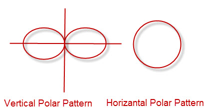
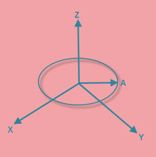
Polar diagram: The most
significant property of an antenna is its radiation pattern or polar
diagram. In case of a transmitting antenna, this is a plot that
discusses about the strength of the power field radiated by the antenna
in various angular directions as shown in the plot below. A plot can
also be obtained for both vertical and horizontal planes – and, it is
also named as vertical and horizontal patterns, respectively.
Till now we have covered the properties
of antennas, and now we will discuss on different types of antennas that
are used for different applications.
Types of Antennas
Log Periodic Antennas
- Bow Tie Antennas
- Log-Periodic Dipole Array
Wire Antennas
- Short Dipole Antenna
- Dipole Antenna
- Monopole Antenna
- Loop Antenna
Travelling Wave Antennas
- Helical Antennas
- Yagi-Uda Antennas
Microwave Antennas
- Rectangular Micro strip Antennas
- Planar Inverted-F Antennas
Reflector Antennas
- Corner Reflector
- Parabolic Reflector
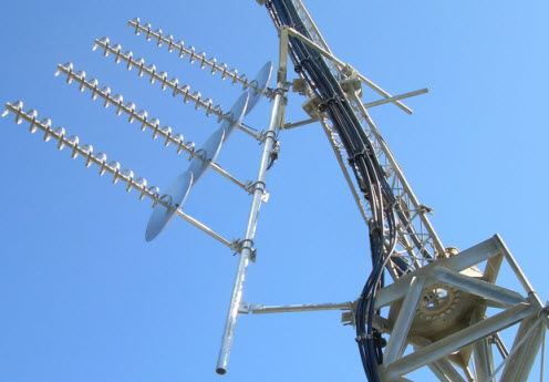
1. Log-Periodic Antennas
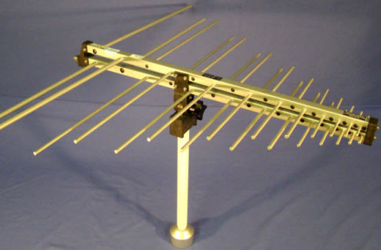
Log Periodic Antenna
A log-periodic antenna is also named as a
log periodic array. It is a multi-element, directional narrow beam
antenna that works on a wide range of frequencies. This antenna is made
of a series of dipoles placed along the antenna axis at different space
intervals of time followed by a logarithmic function of frequency.
Log-periodic antenna is used in a wide range of applications where
variable bandwidth is required along with antenna gain and directivity.
Bow-Tie Antennas
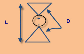
Bow Tie Antenna
A bow-tie antenna is also known as
Biconical antenna or Butterfly antenna. Biconical antenna is an
omnidirectional wide-band antenna. According to the size of this
antenna, it has low- frequency response, and acts as a high-pass filter.
As the frequency goes to higher limits, away from the design frequency,
the radiation pattern of the antenna gets distorted and spreads.
Most of the bow-tie antennas are
derivatives of biconical antennas. The discone is as a type of
half-biconical antenna. The bow-tie antenna is planar, and therefore,
directional antenna.
Log-Periodic Dipole Array
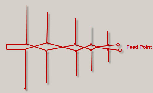
Log Periodic Dipole Antenna
The most common type of antenna used in wireless communication technology
is a log-periodic dipole array fundamentally comprises a number of
dipole elements. These dipole-array antennas reduce in size from the
back end to the front end. The leading beam of this RF antenna comes
from the smaller front end.
The element at the back end of the array
is large in size with the half wavelength operating in a low-frequency
range. The spacing of the element gets reduced towards the front end of
the array wherein the smallest arrays are placed. During this operation,
as the frequency varies, a smooth transition takes place along the
array of the elements, which leads to form an active region.
2. Wire Antennas
Wire Antenna
Wire antennas are also known as linear
or curved antennas.These antennas are very simple, cheap and are used in
a wide range of applications.These antennas are further subdivided into
four as explained below.
Dipole Antenna
A dipole antenna is one of the most
straightforward antenna alignments. This dipole antenna consists of two
thin metal rods with a sinusoidal voltage difference between them. The
length of the rods is chosen in such a way that they have quarter length
of the wavelength at operational frequencies. These antennas are used
in designing their own antennas or other antennas. They are very simple
to construct and use.
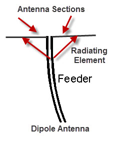
The dipole antenna consists of two
metallic rods through which current and frequency flow. This current and
voltage flow makes an electromagnetic wave and the radio signals get
radiated. The antenna consists of a radiating element that splits the
rods and make current flow through the center by using a feeder at the
transmitter out that takes from the receiver.The different types of
dipole antennas used as RF antennas include half wave, multiple, folded, non-resonant, and so on.
Short-Dipole Antenna:
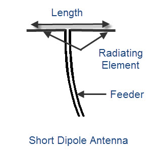
Short Dipole Antenna
It is the simplest of all types of
antennas. This antenna is an open circuited wire in which short denotes “
relative to a wavelength” so this antenna gives priority to the size of
the wire relative to the wavelength of the frequency of operation. It
does take any consideration about the absolute size of the dipole
antenna. The short dipole antenna is made up of two co-linear conductors
that are placed end to end, with a small gap between conductors by a
feeder. A Dipole is considered as short if the length of the radiating
element is less than a tenth of the wavelength.
L<λ/10
The short dipole antenna is made of two
co-linear conductors that are placed end to end, with a small gap
between conductors by a feeder.
The short dipole antenna is infrequently
satisfactory from an efficiency viewpoint because most of the power
entering this antenna is dissipated as heat and resistive losses also
become gradually high.
Monopole Antenna
A monopole antenna is half of a simple dipole antenna located over a grounded plane as shown in the figure below.
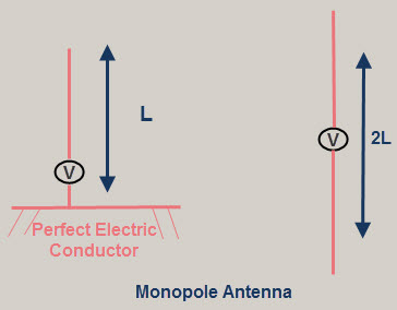
The
radiation pattern above the grounded plane will be same as the half
wave dipole antenna, however, the total power radiated is half that of a
dipole; the field gets radiated only in the upper hemisphere region.
The directivity of these antennas become double compared to the dipole
antennas.
The monopole antennas are also used as
vehicle mounted antennas as they provide the required ground plane for
the antennas mounted above the earth.
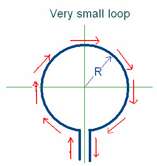
Loop Antenna
Loop Antenna
Loop antennas share similar
characteristics with both dipole and monopole antennas because they are
simple and easy to construct. Loop antennas are available in different
shapes like circular, elliptical, rectangular, etc. The fundamental
characteristics of the loop antenna are independent of its shape. They
are widely used in communication links with the frequency of around 3
GHz. These antennas can also be used as electromagnetic field probes in
the microwave bands.
The circumference of the loop antenna
determines the efficiency of the antenna as similar to that of dipole
and monopole antennas. These antennas are further classified into two
types: electrically small and electrically large based on the
circumference of the loop.
Electrically small loop antenna———> Circumference≤λ⁄10
Electrically large loop antenna ———> Circumference≈λ
Electrically small loops of a single
turn have small radiation resistance compared to their loss resistance.
The radiation resistance of small loop antennas can be improved by
adding more turns. Multi-turn loops have better radiation resistance
even if they have less efficiency.
Small Loop Antenna
Due to this, the small loop antenna are
mostly used as receiving antennas where losses are not mandatory. Small
loops are not used as transmitting antennas due to their low efficiency.
Resonant loop antennas are relatively
large, and are directed by the operation of wavelength .They are also
known as large loop antennas as they are used at higher frequencies,
such as VHF and UHF, wherein their size is convenient. They can be
viewed as folded-dipole antenna and deformed into different shapes like
spherical, square, etc., and have similar characteristics such as
high-radiation efficiency.
3. Travelling Wave Antennas
Helical Antennas
Helical antennas are also known as helix
antennas. They have relatively simple structures with one, two or more
wires each wound to form a helix, usually backed by a ground plane or
shaped reflector and driven by an appropriate feed. The most common
design is a single wire backed by the ground and fed with a coaxial
line.
In General, the radiation properties of a
helical antenna are associated with this specification: the electrical
size of the structure, wherein the input impedance is more sensitive to
the pitch and wire size.
Helical Antenna
Helical antennas have two predominate
radiation modes: the normal mode and the axial mode. The axial mode is
used in a wide range of applications. In the normal mode, the dimensions
of the helix are small compared to its wavelength. This antenna acts as
the short dipole or monopole antenna. In the axial mode, the dimensions
of the helix are same compared to its wavelength. This antenna works as
directional antenna.
Yagi-Uda Antenna
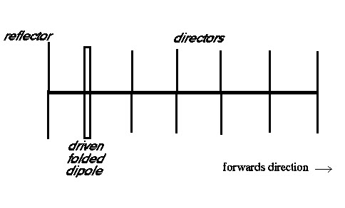
Yagi-Uda Antenna
Another antenna that makes use of passive elements is the Yagi-Uda antenna.
This type of antenna is inexpensive and effective. It can be
constructed with one or more reflector elements and one or more director
elements. Yagi antennas can be made by using an antenna with one
reflector, a driven folded-dipole active element, and directors, mounted
for horizontal polarization in the forward direction.
4. Microwave Antennas
The antennas operating at microwave frequencies are known as microwave antennas. These antennas are used in a wide range of applications.
Rectangular Micro strip Antennas
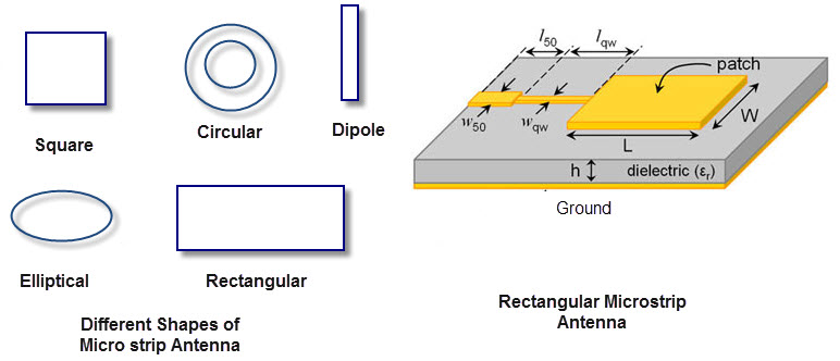
Rectangular Micro strip Antennas
For spacecraft or aircraft applications –
based on the specifications such as size, weight, cost, performance,
ease of installation, etc. – low profile antennas are preferred. These
antennas are known as rectangular microstrip antennas or patch antennas;
they only require space for the feed line which is normally placed
behind the ground plane. The major disadvantage of using these antennas
is their inefficient and very narrow bandwidth, which is typically a
fraction of a percent or, at the most, a few percent.
Planar Inverted-F Antennas
A Planar Inverted-F Antenna can be
considered as a type of linear Inverted F antenna (IFA) in which the
wire radiating element is replaced by a plate to increase the bandwidth.
The advantage of these antennas is that they can be hidden into the
housing of the mobile when compared to different types of antennas like a
whip, rod or helical antennas, etc. The other advantage is that they
can reduce the backward radiation towards the top of the antenna by
absorbing power, which enhances the efficiency. They provides high gain
in both horizontal and vertical states. This feature is most important
for any kind of antennas used in wireless communications.
5. Reflector Antennas
Corner Reflector Antenna
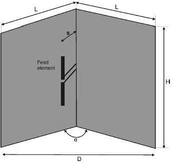
Corner Reflector Antenna
The antenna that comprises one or more
dipole elements placed in front of a corner reflector, is known as
corner-reflector antenna.The directivity of any antenna can be increased
by using reflectors. In case of a wire antenna, a conducting sheet is
used behind the antenna for directing the radiation in the forward
direction.
Parabolic-Reflector Antenna
The radiating surface of a parabolic
antenna has very large dimensions compared to its wavelength. The
geometrical optics, which depend upon rays and wavefronts, are used to
know about certain features of these antennas. Certain important
properties of these antennas can be studied by using ray optics, and of
other antennas by using electromagnetic field theory.
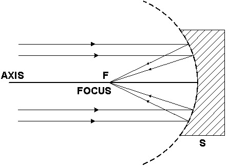
Parabolic Antenna
One of the useful properties of this
antenna is the conversion of a diverging spherical wavefront into
parallel wave front that produces a narrow beam of the antenna. The
various types of feeds that use this parabolic reflector include horn
feeds, Cartesian feeds and dipole feed.
In this article, you have studied about
the different types of antennas and their applications in wireless
communications and the usage of Antennas in transmitting and receiving
data. For any help regarding this article, contact us by commenting in
the comment section below.


No comments:
Post a Comment