


In our day-to-day life, we use to communicate with others frequently using multiple types of communication systems.
This communication system can be classified into different types, such
as a Radio communication system, Telecommunication system, Wireless communication system,
Optical communication system, and so on. For all these communication
systems to operate efficiently, we require a few control systems such as
a Phase- locked loop, Cooperative control, Networked control and so on.
What is Phase-Locked Loop (PLL)?
Phase-locked loop is used as a control system to control different operations in many communication systems, computers and many electronic applications. It is used to generate an output signal which has a phase related to input signal phase.
There are different types of PLLs such as Analog or Linear PLL, Digital PLL, Software PLL, Neuronal PLL and all digital PLL.
Phase Locked Loop Operation
In communication systems, the PLL operation can be explained by considering analog and digital systems.
Analog Phase-Locked Loop in Communication Systems
Basically PLL is a form of servo loop
and a basic PLL consists of three major elements, namely phase
comparator/detector, loop filter and voltage controlled oscillator.
Phase Locked Loop
The major concept behind the PPL
operation is comparision of the phases of two signals (generally input
and output signal phases are compared). Thus, the phase difference
between the input and output signal can be used for controlling the loop
frequency. Even though mathematical analysis is very complicated, but
the operation of the PLL is very simple.
In many communication systems, PLL is used for different purposes:
- For following the phase or frequency modulation, it is used as Demodulator.
- To track or synchronize the two signals with different frequencies.
- To remove large noises from tiny signals.
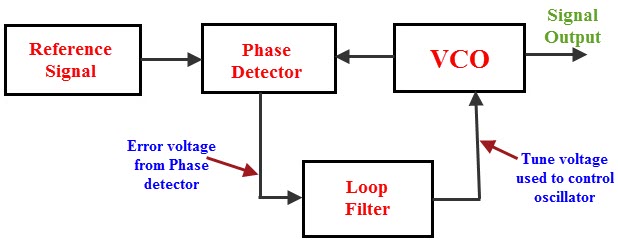
The below figure shows the basic PLL which consists of Phase Detector, Voltage Controlled Oscillator (VCO), Loop Filter.
The voltage-controlled oscillator of PLL
produces a signal and this signal from the VCO is given to the phase
detector. The phase detector compares this signal with the reference
signal and thus, produces an error voltage or difference voltage. This
error signal of the phase detector is fed to the low-pass filter for
removing high-frequency elements of the signal -if any, and for
governing many properties of the loop. Then, the output of the loop
filter is fed to supply the tuning voltage for the control terminal of
the voltage controlled oscillator.
The change in this tuning voltage is
sensed to reduce the phase difference between the two signals (input and
output) and thus, the frequency between them. Initially the PLL does
not lock and the error voltage drags the VCO frequency towards the
reference until the error can not be reduced any further and then the
loop gets locked.
The actual error between the two signals (input and output) is reduced to very small levels using an amplifier
in between the voltage-controlled oscillator and a phase detector. If
the PLL is locked, then a steady-state error voltage will be produced.
This steady-state error voltage represents that there is no phase
difference change between the reference signal and VCO. Thus, we can say
that the frequency of the two signals (input and output signals) is
exactly same.
Digital Phase Locked Loop in Communication systems
In general analog PLLs consists of an
analog-phase detector, voltage- controlled oscillator and low-pass
filter. Similarly, the digital-phase locked loop consists of a
digital-phase detector, a serial-shift register, a stable- local clock signal.
Digital Phase Locked Loop
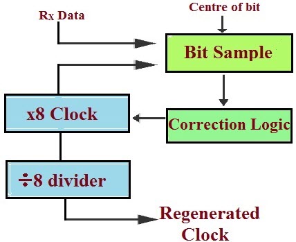
The digital input samples are extracted
from the received signal and these samples are received by the serial
shift register, which is driven by clock pulses supplied from a
local-clock signal. A Phase-corrector circuit that takes local clock is
used to regenerate a stable-clock signal in phase with the received
signal by slow phase adjustment to match the received signal phase.
This adjustment can be done based on a
high-speed sample of each bit using a correction logic. The received
signal sample obtained by the sampling of the received signal at local
clock speed is placed in the shift register.
The required phase adjustment can be
detected by observing the set of samples of the received signal. The two
clocks are said to be in phase if and only if the center of the
received bit lies at the center of the shift register. Phase adjuster is
intended to compensate if the regenerated clock lags or leads the
reference signal.
Application of Phase Locked Loop
- PLLs are frequently used for the purpose of synchronization and for bit synchronization, symbol synchronization, coherent demodulation and threshold extension in space communication.
- The frequency modulated signals can be demodulated using the PLL.
- The new frequency which is a multiple of reference frequency in radio communication transmitters, and synthesized by maintaining the stability of reference frequency with new frequency can be achieved by PLLs.
- There are numerous application for PLLs in many communication systems, computers and many electronic circuits.
- The below application of PLL describes the usage of PLL as voltage to frequency converter.
Voltage to Frequency Converter (VFC) Using a PLL
In communication systems, it is required
to send signals (consider an analog signal here) to a long distance
with full accuracy. For this purpose, a voltage-to-frequency converter
is used, as it is easy to send a frequency signal without causing any
interference over a long distance using optical isolators, coaxial or
twisted-pair lines, radio links, optical fiber links.
There are two types of voltage-to-frequency converters namely multivibrator type VFC and charge balance type VFC.
Multivibrator Type VFC
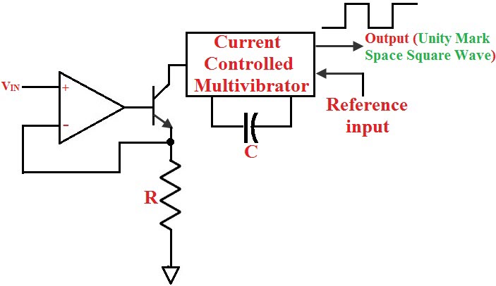
Multivibrator VFC
In the multivibrator type VFC, the
capacitor is charged and discharged using the current obtained from the
input voltage. Stable reference input is given to set switching
thresholds, and the output frequency is proportional to the input
voltage and have unity mark-space ratio.
Charge Balance type VFC
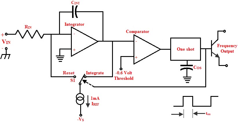
Charge Balance VFC
The charge balance VFC consists of an
Integrator, a Comparator and a precision Charge source.Whenever an input
is given to the integrator, it gets charged and if the output of this
integrator reaches the comparator threshold, then the charge source is
triggered and fixed charge is removed from the integrator. The charge
removed rate must be equal to the charge supplied rate such that, the
charge source triggered frequency and the input to the integrator will
be proportional to each other.
Thus, this article gives a brief description about the phase locked loop system
in the communication system. Further, this article can be extended
technically based on your suggestions and queries. Hence, you can
approach us for any technical assistance by posting your comments below.


No comments:
Post a Comment