


This article is for all those electronics enthusiasts eager to fidget with the basic components in electronics, available all around. So here are 10 very simple yet interesting electronic projects.
1. Crystal Tester
Crystal is used as an oscillator, to
generate a high frequency. In all the major electronic projects crystal
is used instead of coil. It is easy to test a coil using a multimeter
but it is quite tough to test a crystal. So in order to overcome this
problem this simple project is designed using few passive components for
testing the crystal.
 Circuit Connection
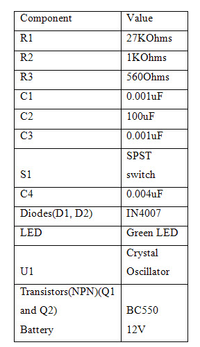
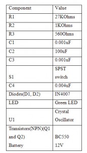
This electronic circuit consists of a
crystal oscillator, two capacitors and a transistor forming a Colpitt
oscillator. A combination of diodes and capacitors are used for
rectification and filtering respectively. Another NPN transistor is used
as a switch to make the LED glow.
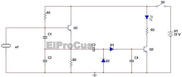
Crystal Tester Circuit Diagram
Circuit Operation
The entire circuit is operated with two
transistors, two diodes, and few passive components. If the testing
crystal is good then it operates as an oscillator in combination with
transistor. The diode rectifies the output of the oscillator and the
capacitor filters the output. This output is now fed to the base of the
transistor and the transistor starts conducting.
An LED is connected to the collector of
the transistor through the resistor. The LED gets proper biasing and
starts emitting light, i.e. it starts glowing. In case if any fault
occurring in the testing crystal then the LED does not glow.
2. Battery Voltage Monitor
This electronic project is used to
monitor the charging and discharging of the battery such that the
battery voltage doesn’t exceed the specific level of that battery. It
basically acts as a controlled battery charger. It indicates the state of the battery.
 Circuit Connections
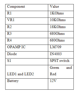
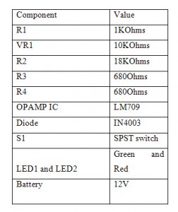
The circuit of the battery voltage monitor is implemented using an operational amplifier
IC (LM709) which is used as a comparator. Here a bi color LED is used
to indicate the status of the battery. A combination of a resistor and a
potentiometer is used as a potential divider.
The voltage at this potential divider is
fed to the inverting input pin of the comparator. The resistor R3 and
R4 is used as current limiter of the LED.
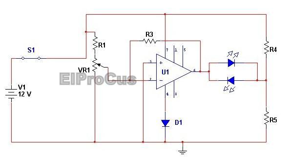
Battery Voltage Monitor Circuit Diagram
Circuit Operation
The entire electronic circuit is powered
by 12V battery. When the voltage level of the battery increases up to
13.5 volts, the voltage at the inverting input is less than then voltage
at the non inverting input and the output of the OPAMP goes low. LED1
begins to emit red light which indicates that battery is over charged.
When the voltage level of the battery
falls to 10volts, the voltage at the inverting terminal is less than the
voltage at the non inverting terminal. The OPAMP output goes high. LED2
begins to emit GREEN light which indicates that the battery needs to be
charged.
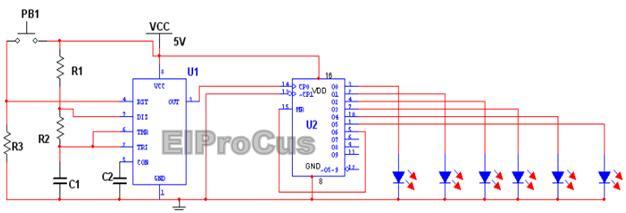
3. LED Indicator Light
This project is used to design an indicator using LEDs. It is an inexpensive electronic project and can replace the traditional indicators used in bikes and cars.Circuit Components
 Circuit Connection
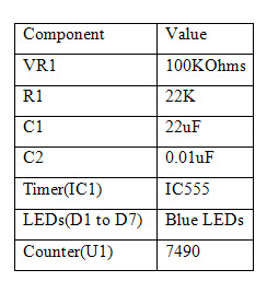
A 555 timer
is used in astable mode to generate clock pulses. The trigger pin of
the timer is shorted to the threshold pin. A BCD counter IC 7490 is used
to indicate the pulse count by switching on/off the LEDs. The LEDs are
connected to the output of the counter IC.
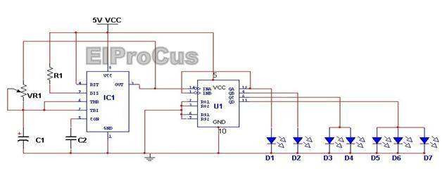
LED Indicator Light Circuit Diagram
Circuit Operation
The pulses generated by the 555 timer
are fed to the clock input of the counter. The counter accordingly
generates a high signal at each of its output pins based on the number
of the pulses received. For a high signal at any output pin, the
connected LED glows. When the counter starts progressing, the light
appears to move towards left.
If the frequency of the pulses
increases, then the light emitted by the LEDs appears to move in one
particular direction. If the frequency is high then the LED’s appears to
glow at an instant. Individual flicker is eliminated as the light
appears to move left at a faster rate.
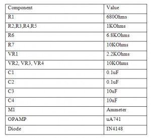
4. Electronic Thermometer
This is one of the simple electronic
projects where an electronic thermometer is designed. It can be used for
measuring wide range of temperature. This thermometer can replace the
clinical thermometer used by doctors.
 Circuit Connection
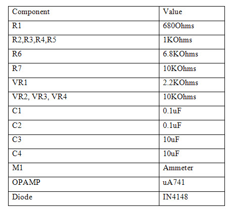
A 9V battery is used as the DC power
supply source for the entire circuit. A diode is used as a temperature
sensor and is connected in feedback path of an operational amplifier. The
input voltage is fixed by VR1, R1, and R2 at the non inverting pin 3 of
the op-amp IC1. The output from this IC1 is fed to the inverting
terminal of another OPAMP IC2. The non inverting terminal of this OPAMP
is given a fixed voltage signal. The output from this IC is connected to
an ammeter which shows the current reading which is calibrated to show
temperature.
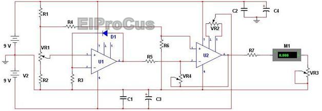
Electronic Thermometer Circuit Diagram
Circuit Operation
The voltage drop across the diode
changes with change in temperature. At room temperature, the voltage
drop across the diode is 0.7V and reduces at the rate of 2mV/degree
Celsius. This voltage change is sensed by the operational amplifier. The
output of the operation depends upon the voltage drop across the diode.
Here another Operational amplifier is
used as voltage amplifier. The output from IC1 is amplified by the
operational amplifier IC2. The ammeter indicates the current amplitude
of the output signal and this is calibrated to indicate the value of the
temperature.
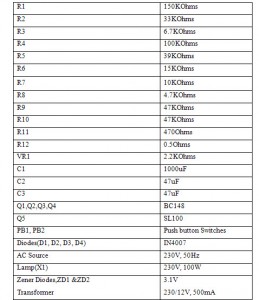
5. Electronic Motor Controller
This electronic circuit is designed for
controlling the motor using electronic devices. It is more efficient
than any electromechanically controlling device. This project is also
designed to eliminate the problems of noise triggering and noise pulses.
These types of electronic projects are very simple and easy to be
constructed and implemented. Here, we have demonstrated lamp intensity
control instead of motor control.
 Circuit Connections
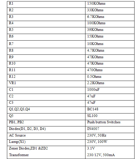
The secondary of the transformer is
connected to the diodes. The diode D1 and D2 are used for rectification
and the capacitor is used as noise filter of the switching circuit. Here
5 transistors are biased in common emitter mode. The transistors Q1,
Q2, Q3 are used to detect any fluctuations in voltage. The output of
transistor Q1 is given to transistor Q2. The output from transistor Q2
is given to the base of transistor Q3 and the output from transistor Q4
is fed to the base of transistor Q4. The collector of transistor Q5 is
connected to a relay.
Here a 2 CO relay is used. A reverse
biased diode is also connected to the relay (at its other point). The
resistor network R11, R12, VR1 forms a current sensor circuit.
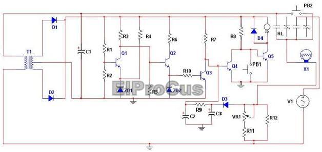
Electronic Motor Control Circuit Diagram
Circuit Operation
The entire circuit is power by pressing
the switch SW1. When the switch sw1 is pressed the transformer gets
mains voltage supply and converts it into low voltage. The current
through the resistor R8 gives base current to the transistor T5.
When the relay gets activated the motors
also switches on. The current sensor senses the logic high signal. When
the transistor T4 receives a logic high signal from the current sensor,
the R8 resistor gives low signal to the transistor T5 and the
transistor will not conduct.
As a result the relay does not get
energized and the motor is switched off. SW2 switch is used to switch
off the motor. The transistor T4 gets on when the over and under voltage
is given to the T3 transistor. The capacitor C2 and R10 resistor
together forms a low pass filter for avoiding noise triggering and
pulses. It also provides sufficient time delay to the circuit.
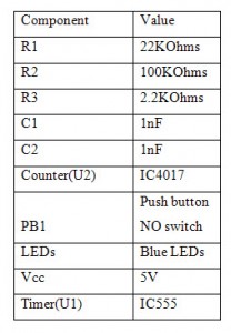
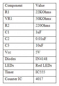
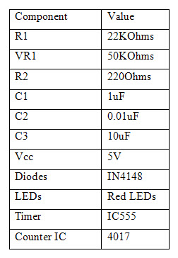
6. Electronic Dice
A dice is a cube which is often used in
many indoor games. Clearly a dice needs to be unbiased. Conventional
dices used often get biased due to certain deformations or any defects
in the construction. Here in this electronic project, an electronic dice is built which will always remain unbiased and would provide accurate reading.
 Circuit Connection
Here a 555 timer is connected in astable mode. A resistor of 100K is
connected between pins 7 and8. A resistor of 100K is connected between
pins 7 and 6. The output from the timer at pin 3 is connected to the
clock input pin of the counter IC 4017.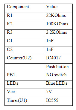
Circuit Diagram
Electronic Dice Circuit Diagram
Circuit Operation
With proper values of the resistor and
capacitor, the 555 timer generates clock pulses at a frequency of 4.8
KHz, i.e. a clock cycle of quite low time period. When these pulses are
fed to the counter, each output pin goes high according to the number of
pulses. The LED connected to each pin starts glowing as the pin goes
high. In other words the LEDs start glowing for each corresponding
count. The switching of the LEDs is at such a fast rate that it cannot
be perceived by human eye. The counter resets automatically as the count
advances to 7.
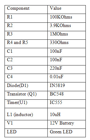
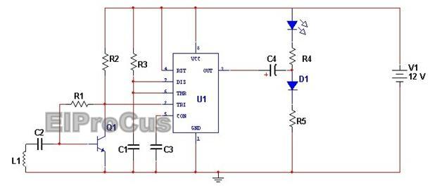
7. Automatic car head lights turn OFF Circuit
This electronic circuit saves the
battery energy while the car ignition switch is turned OFF. It reduces
the need for checking whether the head lights are ON/OFF. We can also
vary the time for turn OFF the lamps by the varying the potentiometer
connected to the timer IC.
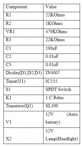 Circuit Connection
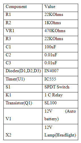
This circuit mainly comprises of 555
timer IC, NPN transistor and the relay. Timer IC is connected in the
mono stable mode of operation. In this mode timer requires a trigger
input to generate the pulse with a certain time period. Output from the
timer IC is connected to an NPN transistor. The collector of this
transistor is connected to one terminal of a relay coil. Relay is used
to control ON/OFF periods of the lamp.
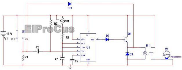
Automatic Car Headlights Circuit Diagram
Circuit Operation
An ignition switch acts as a triggering
pulse to the timer. When the ignition is switched ON, a high logic
signal is fed to the trigger pin of the timer and the timer doesn’t
produce any output. The diode as well as the transistor doesn’t conduct.
The relay coil gets energized as it is connected to proper supply and
headlights get switched on. When the ignition switch is turned OFF, a
low logic pulse is given to the second pin of the timer so the output of
the timer goes HIGH for time period which is set by the RC values. The
relay coil will be energized and the lamp will glow, but for a certain
minimum time period and then will be switched off.
8. Fire Alarm Circuit
This simple electronic circuit is designed to give an alarm incase when fire breaks out. This circuit works on the principle that ambient temperature increases as fire breaks out and this temperature changed is sensed and processed to give an alarm signal.Circuit Components
 Circuit Connection
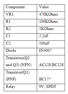
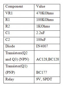
Here a PNP transistor is used as a fire
sensor and its collector is connected to the base of a NPN transistor
through a series combination of a potentiometer and a resistor. The
emitter of this NPN transistor is connected to the base of another
transistor. The emitter of this transistor is connected to a relay. A
diode is connected across the relay for back EMF protection. This relay
is used to control the switching of the load, which can be a horn or a
bell.
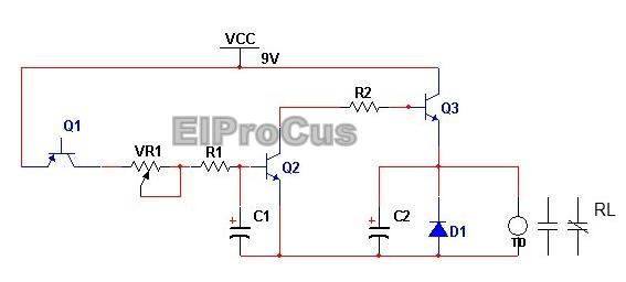
Fire Alarm Circuit Diagram
Circuit Operation
When fire breaks out, the temperature
increases. This causes the leakage current of the PNP transistor Q1 to
increase. As a result transistor Q2 will be biased and starts
conducting. This in turn brings transistor Q3 to conduction. The
collector and emitter terminals of this transistor are shorted and
current flows from the DC power supply to the relay coil. The relay coil
gets energized and the load gets switched on.
9. Mobile Incoming Call Indicator
This circuit is designed to give an indication for incoming call on a cell phone.
This electronic project proves to be a relief from the nuisance created
due to the sudden ringing of the mobile. There are many situations
where we cannot switch off the mobile nor put it in silent mode, yet a
loud ring can prove to be very embarrassing. This circuit proves to be a
relief in such situations.
 Circuit Connection
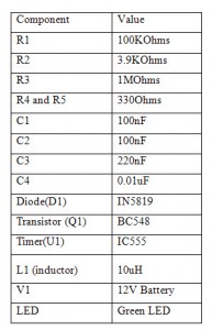
A coil is connected with a capacitor to
the base of an NPN transistor. The collector of this NPN transistor is
connected to the trigger pin of the timer IC555. This timer IC is
connected in mono stable mode with a resistor of 1M connected between
pins 7 and 8. The output of the timer at pin 3 is connected to the anode
of the LED and the cathode of the diode. This whole circuit is powered
by a 9V battery.
Mobile Incoming Call Indicator Circuit Diagram
Circuit Operation
When the mobile receives an incoming
call, its transmitter generates a signal around 900MHZ. This
oscillation is picked up by the coil in the circuit. As current flows
from the coil to the base of the transistor, it conducts. As the
transistor conducts, i.e. gets switched on, the collector and emitter
are shorted and connected to ground. This gives a low logic signal to
the trigger pin of the timer and the timer is triggered. A high logic
signal is produced at the output of the timer. The LED gets proper
biasing and starts blinking. This blinking of the LED indicates the
incoming call.
10. LED Knight Rider Circuit
LED Knight rider running circuit is a
light chaser or running light effect generator which produces forward
and reverse moving effects. This type of lighting is used mainly in the
automotive applications and other sequential type of lighting
applications. It is one of the application circuits of IC 4017.
 Circuit Connection
This circuit comprises of two IC’s i.e.,
timer IC and decade counter IC. 555 timer IC generates the clock pulses
which are fed to the clock signal of the decade counter IC. The rate at
which the lights are glowing depends on the RC time constant or clock
frequency of the timer. Decade counter IC 4017 has ten outputs which go
on high in sequence when pulses are applied at the clock input. These
LED’s are connected through the diodes to produce the to and fro
chasing.

LED Indicator light Circuit Diagram
Circuit Operation
555 timer IC is connected in astable
mode so that it will continue to generate the pulses at a rate fixed by
the RC values connected to it. These pulses are applied to the 4017 IC
so the outputs of this IC are sequentially tuned ON at rate fixed by the
timer. Initially the LEDs are switched on in increasing order and as
the last LED gets switched on, the switching of the LEDs occur in
reverse order.
In other words, the first 6 outputs are
connected directly to the LEDs to produce sequential switching of the
LEDs and the next 4 outputs are connected to each LED so as to produce a
reverse lighting effect. By varying the potentiometer at the timer we
can get the variable rate of the LED’s switching.
So simple and basic circuits,
isn’t it? Don’t you find all these electronic projects worth to be
implemented at your home or used as ? Of course, I guess. So there is
this one little task for you. Amongst all these projects, pick up one
which catches your attention and try to make some changes in it.
Post these changes as well as your observations in the comment section below.
please follow the below link: 5 in 1 solderless project


No comments:
Post a Comment