


Consider a situation in a bank or any
organization where a sudden invasion by the burglars has taken place.
Now all the staff has been handcuffed by the robbers and the main locker
room full of valuable resources is at the mercy of the robbers. So is
there any way to prevent this theft?? Yes, there is, if any buzzer is
connected which can start ringing, alarming the local police or a camera
fitted along with a GSM modem that can send the video to the police
stations. But still the problem lies in the way to switching on these
devices.
Consider another situation, when a
person is at his room (in a hostel or a hotel) and a thief tries to
enter the room at night when the room is dark and the owner is fast
asleep. There needs to be a system for automatic switching on of the light and ringing of the buzzer alarm.
In both these situations, the solution
lies in devising a way for automatic operation of a switch and to
achieve this, one of the most efficient ways is a Sound Operating
switch.
Two ways to design your own sound operated switch
- Using a audio Amplifier and a timer
A basic sound operating switch can be
constructed using an audio amplifier IC, a comparator, a 555 timer
operating in monostable mode, a relay and a load. Here the basic idea is
to change the output of the timer with input from the microphone, in
order to switch on the load. The load can be a incandescent lamp or a
LED lamp or a motor.
The audio signal is received by the
microphone, which converts the audio signal to electrical signals. The
signal is given to the pin2 of comparator IC 741. The other input pin 3
of the comparator is given by the reference voltage set by the
potentiometer arrangement.
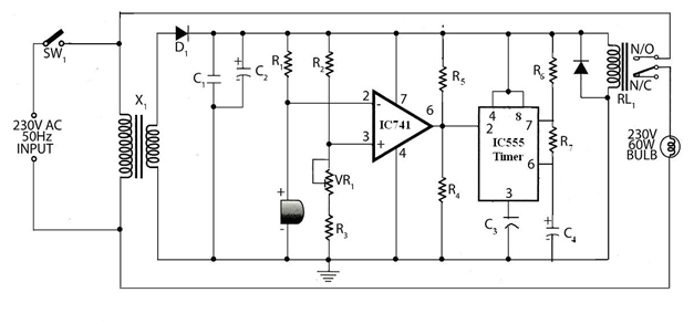
Simple Sound Operated Switch circuit
In absence of any audio signal, pin 2 is
at logic high and the output of comparator is at logic low, giving a
low signal to the trigger pin of the 555 timer. The output of the timer
is thus at logic high, keeping the relay at off condition. When a sound
is heard the microphone detects it and converts it to electrical signal
and the signal is applied to pin2 of the comparator and since this pin
is now at logic low, the comparator output is at logic high, triggering a
logic high signal to the trigger pin of the timer. The timer output is
thus at logic low, driving on the relay, which in turn switches on the
load( A bulb) for a time determined by the RC combination.
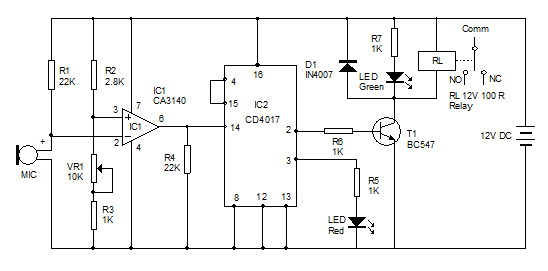
- A Sound Operated Switch using Counter IC
You can use this circuit to operate a
Relay through the sound of claps. It is highly sensitive and can detect
the sound of the clap from a distance of 1-2 meters. AC loads such as
lamps, fans etc can be connected through the relay. This circuit has
three sections. A sensitive MIC amplifier, A Toggle switch based on IC
CD4017 and a Relay driver. IC CD4017 is a decade counter where the
output count number is shown by the corresponding output number pin
going high.
Condenser Microphone picks up the sound
vibrations and generates minute voltage across its terminals. These
feeble signals are amplified by IC1. Resistor R1, R3 and variable
resistor VR1 adjust the sensitivity of the amplifier. Resistor R1 set
the sensitivity of Mic. The amplified output pulses from IC1 passes to
the input of IC2 (CD 4017). Resistor R4 keeps the input (pin14) of IC2
low so as to prevent false triggering. IC2 is a decade counter IC which
is wired as a toggle switch. That its outputs 1 and 2 (pins 2 and 3)
becomes high and low alternately when the input pin14 receives pulses
from IC1. Pin4 (output4) is connected to the reset pin15 so that
further counting will be inhibited. The high output from IC2 passes
through the current limiter R6 to the base of switching transistor T1.
When T1 conducts, Green LED and the Relay turns on. In the next clap,
output pin 2 becomes low to switch off the relay and the Green LED. Red
LED indicates the OFF position of the load.
In other words, when we first make a
clapping sound, the audio signal gets converted by the microphone to
electrical signal and amplified by the operational amplifier, which
gives the output pulse. When the counter receives the first pulse the
pin 2 goes high and the relay driver is switched on to energize the
relay and thus switch on the LED. When we again make a clapping sound,
the amplifier IC generates another pulse. This time the pin 2 goes low
and pin 3 goes high, causing the red LED to glow. The relay is now
switched off and the LED is in off condition.
Note: It is better to connect the
Microphone directly on the PCB using two pieces of the trimmed leads of
resistor or capacitor. If Microphone is connected with wires,
sensitivity may be reduced. Enclosing the Microphone in a tube will
increase the sensitivity considerably. Adjust VR1 to get maximum
sensitivity and range.
4 Sound Operated switches available in the market
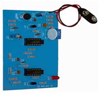
It is a sound operated electronic switch
kit by Electro Kits. It operates on a 9V battery and uses a electrets
microphone. It switches on and off an LED mounted on the kit.
- Automatic Voice Activated Switch

Its switching time is up to 60seconds and supports loads upto 3A-115V or 5A-12V

It is a microprocessor controlled switch
operating on 1 or 2 claps. It has a relay power rating of 24VDC/AC 3A.
It works on a power supply of 12V dc.
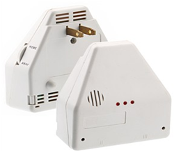
1382313 Model number Sound Operated Switch
It is a 1382313 model number sound
operated switch operating on a power of 250W max with a supply voltage
of 120V. It works in two modes. In Home mode, it can operate one or two
appliances. In the Away mode, it will operate on any noise to switch on
the connected appliance.
Now you have got an idea about how the sound activated switch is used if any queries on this topic or on the electrical and electronic projects leave the comments below.


No comments:
Post a Comment