


This article discusses the
mathematical significance of I/Q signals and presents the final steps in
the DSP algorithm for decoding frequency-shift-keying baseband signals.
Before continuing, please check out our relevant resources and articles to give you more context:
The last computation presented in the previous article on designing a robust FSK decoder was the multiplication of three I/Q baseband signals (representing the binary sequence 0101) with reference symbols used for FSK decoding. The results were as follows:
Phase-Aligned Baseband Signals
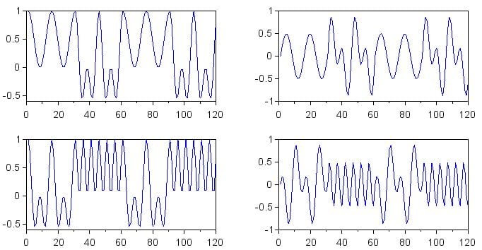
Figure 1
The plots in Figure 1 are for the phase-aligned baseband signals. The multiplication waveforms produced from the I baseband signals are on the left, and the multiplication waveforms from the Q baseband signals are on the right. The results for decoding of a binary 0 are in the top row, and the results for decoding of a binary 1 are in the bottom row.
Baseband Signals with a Phase Shift of 45°
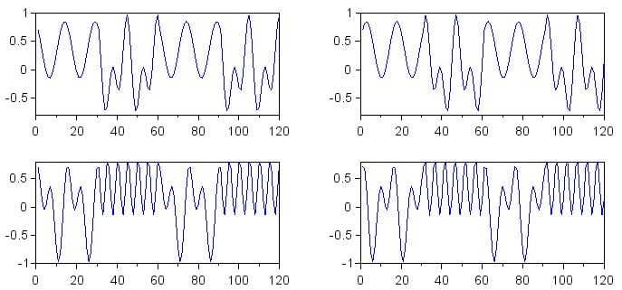
Figure 2
The plots in Figure 2 are for the baseband signals that have a phase shift of 45°. As in Figure 1, I is on the left, Q is on the right, binary 0 decoding is in the top row, and binary 1 decoding is in the bottom row.
Baseband Signals with a Phase Shift of 90°
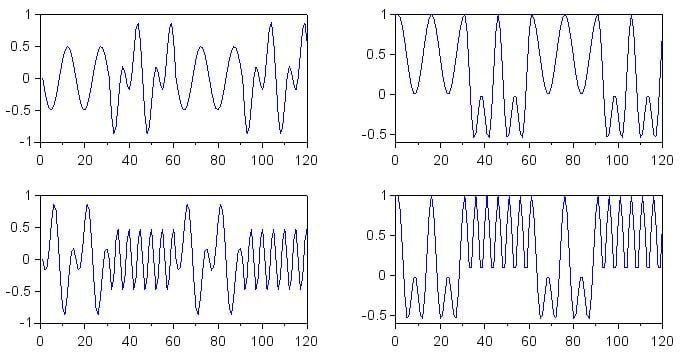
Figure 3
The plots in Figure 3 are for the baseband signals that have a phase shift of 90°. The organization of the plots is the same as in the previous two figures.
Assessing the Plots
Our goal here is to make a system that will generate a relatively large DC offset when the frequency of the received signal is very similar to the frequency of the reference signal, regardless of the phase relationship between these two signals.For now, let’s look only at the top-left plot, which shows binary 0 decoding of the received I signal.
In Figure 1, there is a large DC offset corresponding to the first and third symbols, which are binary 0 symbols. In Figure 2, the 45° phase difference between received signal and reference signal has caused the DC offset of the binary 0 symbols to decrease; the offset is still fairly large, though. In Figure 3, the 90° phase difference between received signal and reference signal has eliminated the DC offset.
If you observe the changes in the top-right plot, you see the opposite trend: the offset of the binary 0 symbols starts at zero and increases in the second and third figures. This is the “balancing” effect of I/Q processing. By generating two baseband signals that have a phase difference of 90°, we ensure that increasing phase misalignment in one baseband signal is balanced by increasing phase alignment in the other baseband signal.
The plots in the bottom row exhibit the same behavior, but for the binary 1 symbols (i.e., the second and fourth symbols).
I/Q Signals as Complex Numbers
One of the keys to understanding I/Q signal processing is making the connection between I/Q components and complex numbers. I use the word “components” because I waveforms and Q waveforms are, from a mathematical point of view, not really signals in themselves. They are the in-phase and quadrature components of the original signal, and they represent the original signal in the same way that the real and imaginary parts of a complex number represent a vector consisting of a magnitude and an angle.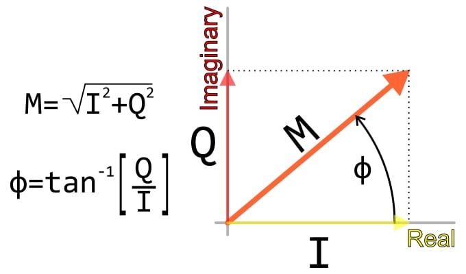
Figure 4
So far, we have been processing the I and Q signals as if they are independent, and this produces results that are somewhat difficult to interpret—we’re essentially looking at complex numbers in rectangular form when what we really want to know is the magnitude.
Thus, to make our I/Q-based algorithm mathematically complete, we need to convert the I and Q components into a magnitude.
How to Find the DC Offset
Let’s make our I/Q data easier to visualize by generating plots corresponding to the three figures shown above, but with each symbol replaced by its DC offset (which, in mathematical terms, is the mean). You may recall that we did the same thing toward the end of a previous article on decoding an FSK signal.for k=1:(length(DecodeZero_I_aligned)/Samples_per_Symbol) > SymbolOffsets_Zero_I_aligned(((k-1)*Samples_per_Symbol)+1:k*(Samples_per_Symbol)) = mean(DecodeZero_I_aligned (((k-1)*Samples_per_Symbol)+1:k*(Samples_per_Symbol))); > end
This for loop is the template for all the rest. You’ll need 12 in total, because we have 12 arrays (corresponding to the 12 plots shown above). The only things that you need to change are the Decode... array and the SymbolOffsets... array. For example:
for k=1:(length(DecodeOne_Q_90deg)/Samples_per_Symbol)
  > SymbolOffsets_One_Q_90deg(((k-1)*Samples_per_Symbol)+1:k*(Samples_per_Symbol)) = mean(DecodeOne_Q_90deg (((k-1)*Samples_per_Symbol)+1:k*(Samples_per_Symbol)));
  > end
I used the following commands (modified as necessary for the other arrays) to plot the data and improve the appearance.
subplot(2,2,1)
plot(SymbolOffsets_Zero_I_aligned)
subplot(2,2,2)
plot(SymbolOffsets_Zero_Q_aligned)
subplot(2,2,3)
plot(SymbolOffsets_One_I_aligned)
subplot(2,2,4)
plot(SymbolOffsets_One_Q_aligned)

f = gcf();
for k=1:4
  > f.children(k).font_size = 3;
  > f.children(k).data_bounds = [0, -0.2; 120, 0.7];
  > f.children(k).children.children.thickness = 2;
  > end
Here are the results. For each set of plots, the results are laid out as follows:
- Top left: decoding zero, I component
- Top right: decoding zero, Q component
- Bottom left: decoding one, I component
- Bottom right: decoding one, Q component.
DC Offsets for the Phase-Aligned Baseband Signals
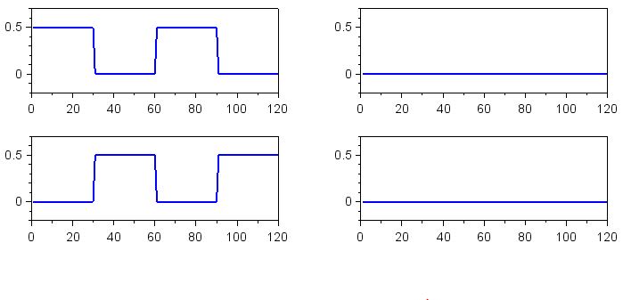
Figure 5
DC Offsets for the Baseband Signals with 45° Phase Shift
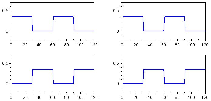
Figure 6
DC Offsets for the Baseband Signals with 90° Phase Shift
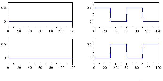
Figure 7
How to Convert from I/Q to Magnitude
The last step in the process of producing phase-independent decoding results is to combine the I and Q offsets into a single decoding value. This can be done as follows:SymbolOffsets_Zero_aligned = sqrt((SymbolOffsets_Zero_I_aligned .* SymbolOffsets_Zero_I_aligned) + (SymbolOffsets_Zero_Q_aligned .* SymbolOffsets_Zero_Q_aligned)); SymbolOffsets_One_aligned = sqrt((SymbolOffsets_One_I_aligned .* SymbolOffsets_One_I_aligned) + (SymbolOffsets_One_Q_aligned .* SymbolOffsets_One_Q_aligned)); SymbolOffsets_Zero_45deg = sqrt((SymbolOffsets_Zero_I_45deg .* SymbolOffsets_Zero_I_45deg) + (SymbolOffsets_Zero_Q_45deg .* SymbolOffsets_Zero_Q_45deg)); SymbolOffsets_One_45deg = sqrt((SymbolOffsets_One_I_45deg .* SymbolOffsets_One_I_45deg) + (SymbolOffsets_One_Q_45deg .* SymbolOffsets_One_Q_45deg)); SymbolOffsets_Zero_90deg = sqrt((SymbolOffsets_Zero_I_90deg .* SymbolOffsets_Zero_I_90deg) + (SymbolOffsets_Zero_Q_90deg .* SymbolOffsets_Zero_Q_90deg)); SymbolOffsets_One_90deg = sqrt((SymbolOffsets_One_I_90deg .* SymbolOffsets_One_I_90deg) + (SymbolOffsets_One_Q_90deg .* SymbolOffsets_One_Q_90deg));
The following commands will plot the results:
subplot(3,2,1)
plot(SymbolOffsets_Zero_aligned)
subplot(3,2,2)
plot(SymbolOffsets_One_aligned)
subplot(3,2,3)
plot(SymbolOffsets_Zero_45deg)
subplot(3,2,4)
plot(SymbolOffsets_One_45deg)
subplot(3,2,5)
plot(SymbolOffsets_Zero_90deg)
subplot(3,2,6)
plot(SymbolOffsets_One_90deg)

f = gcf();
for k=1:6
  > f.children(k).font_size = 3;
  > f.children(k).data_bounds = [0, -0.2; 120, 0.7];
  > f.children(k).children.children.thickness = 2;
  > end
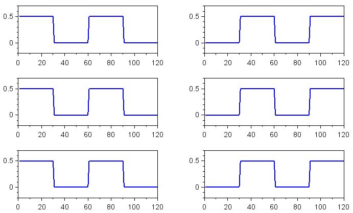
Accurate Decoding, Regardless of Phase Relationship
As you can see, I/Q signal processing has eliminated the effect of phase difference between the received signal and the reference signal. The binary 0 and binary 1 symbols now produce the full DC offset and can be accurately decoded, regardless of the phase relationship between the transmitter and the receiver.I hope that you now understand the value of quadrature modulation in DSP-based FSK decoding and that you have some clear ideas of how you might implement frequency shift keying in a real software-defined RF data link.


No comments:
Post a Comment