


This articles documents how to
build a 12V PC fan PWM controller with Dialog GreenPAK configurable
mixed-signal ICs. The project involves rotary encoding, PWM control, PCB
design, and C# application programming.
The design can control
up to 16 3-pin computer fans, uses a pair of Dialog GreenPAK
configurable mixed-signal ICs to control each fan’s duty cycle,
and includes two ways to change the speed of the fan:- with a quadrature/rotary encoder and
- with a windows application — built in C# that communicates with the GreenPAKs with I2C.
System Block Diagram
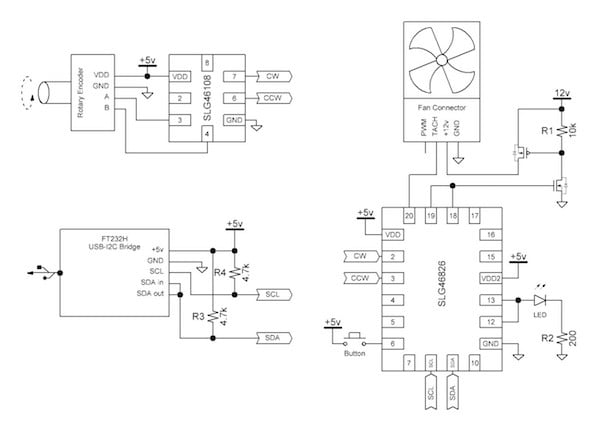
Figure 1. System block diagram
SLG46108 Rotary Decoder Design
To increase or decrease the duty cycle of the fans manually, we used a rotary encoder. This device outputs pulses on its Channel A and Channel B outputs that are 90° apart. See AN-1101: Unclocked Quadrature Decoder for more information about how a rotary encoder works.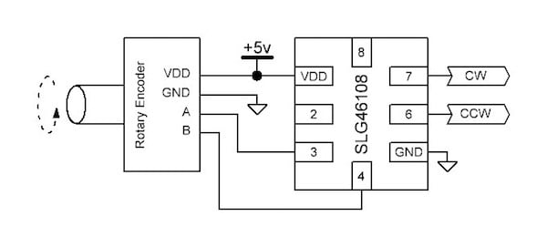
Figure 2. Rotary encoder block diagram
We then created a clocked rotary decoder using a Dialog GreenPAK SLG46108 to process the Channel A and Channel B signals and output them as counterclockwise (CCW) and clockwise (CW) pulses.
When Channel A leads Channel B, the design outputs a short pulse on CW. When Channel B leads Channel A, it outputs a short pulse on CCW.
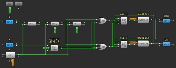
Figure 3. GreenPAK SLG46108 rotary decoder design
We used 3 DFFs to synchronize the Channel A input with the clock. Similarly, we used the pipe delay with OUT0 set to 2 DFFs and OUT1 set to 3 DFFs to create the same functionality for channel B.
We then used a few LUTs to create our CW and CCW outputs. For more information about this standard rotary decoder design, visit this website.
In the end, the GreenPAK Rotary Decoder will receive input pulses A and B in the figure below and output the CW and CCW pulses as shown.
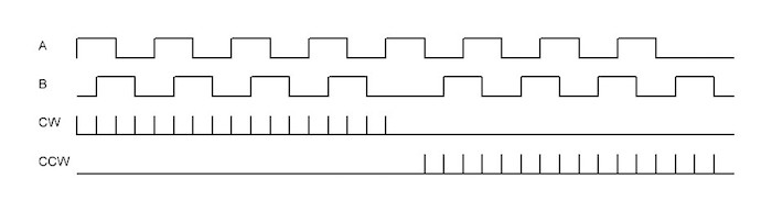
Figure 4. Timing diagram of rotary signals
The circuitry after the XOR gates ensures that there will never be a CW pulse and CCW pulse at the same time in case there is some error with the rotary encoder. The 8ms falling edge delay on the CW and CCW signals force them to stay high for 8ms plus 1 clock cycle, which is necessary for the downstream SLG46826 GreenPAKs.
SLG46826 Fan Controller Design
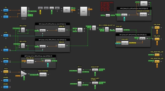
Figure 5. GreenPAK SLG46826 Fan Controller Design
PWM Generation with Offset Counters
To generate the PWM signal we used a pair of offset counters with the same period. The first counter sets a DFF, and the second resets it, creating a consistent duty cycle PWM signal as shown below.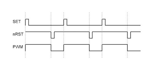
Figure 6. PWM generation timing diagram
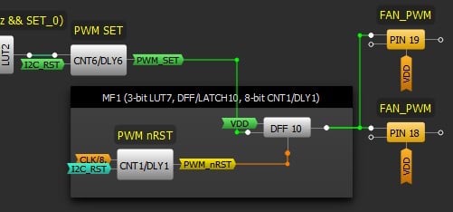
Figure 7. PWM generation with offset counters
CNT6 sets DFF10 and the inverted output of CNT1 resets DFF10. Pins 18 and 19 are used to output the PWM signal to external circuitry.
Duty Cycle Control with Clock Injection and Clock Skipping
The fan controller receives the CW and CCW signals as inputs from the rotary decoder and uses them to either increase or decrease the PWM signal that controls the fan speed. We achieved this with several digital logic components.What we needed to do is make it so that the duty cycle is increased when we receive a CW pulse. We can achieve this by injecting an extra clock pulse into the CNT6 block, causing it to output one clock cycle earlier than it otherwise would have. You can see this process in the timing diagram below.
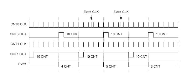
Figure 8. Clock pulse injection
CNT1 is still getting clocked at a constant rate, but CNT6 has a couple of extra clocks injected. Every time there is an extra clock to the counter, it shifts its output one clock period to the left.
Conversely, if we want to decrease the duty cycle, we need to skip a clock pulse for CNT6. You can see that process in the figure below, where CNT1 is still getting clocked at a constant rate, and there are skipped clock pulses for CNT6, where the counter did not get clocked when it was supposed to. This way we can push the output of CNT6 to the right by one clock period at a time and shorten the output PWM duty cycle.
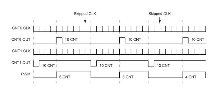
Figure 9. Clock pulse skipping
We achieved the clock injecting and clock skipping functionality with some digital logic elements within the GreenPAK. We used a pair of multifunction blocks to create a pair of latch/edge detector combos. 4-bit LUT0 is used to mux between the general clock signal (CLK/8) and the clock injecting or clock skipping signals. This functionality will be described in more detail in section 5.2.2 Preventing Duty Cycle Rollover.
BUTTON Input
The BUTTON input is debounced for 20 ms, then is used to toggle a latch that will determine whether this particular chip is selected. If it is selected, then the 4-bit LUT will pass the clock skipping or injection signals. If the chip is not selected, then the 4-bit LUT will simply pass the CLK/8 signal.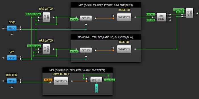
Figure 10. Clock skipping and clock injecting
Preventing Duty Cycle Rollover
The RS latches 3-bit LUT5 and 3-bit LUT3 are used to make sure that you can't inject or skip so many clocks that the offset counters will roll over. We don't want to allow the system to reach 100% duty cycle and then roll over to a 1% duty cycle if it receives another injected clock.The RS latches prevent this from happening by latching the inputs to the multifunction blocks when the system is 1 clock cycle away from rolling over. We used a pair of DFFs to delay the PWM_SET and PWM_nRST signals by one clock period as shown in the figure below.
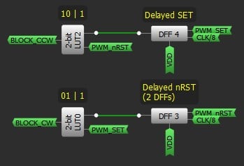
Figure 11. BLOCK_CW and BLOCK_CCW
We then used a pair of LUTs to create the necessary logic. If our duty cycle is so low that the delayed PWM_SET signal occurs at the same time as the PWM_nRST signal, we don't want to decrease the duty cycle any further or we will roll over.
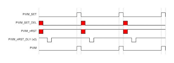
Figure 12. Minimum duty cycle rollover case
Similarly, if we are approaching our maximum duty cycle such that the delayed PWM_nRST signal occurs at the same time as the PWM_SET signal, we don't want to increase the duty cycle any further. In this case we needed to delay the nRST signal by 2 clock cycles to ensure that the system doesn't roll over from 99% to 1%.
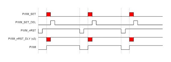
Figure 13. Maximum duty cycle rollover case
Duty Cycle Control with I2C
This design incorporates another way to control the duty cycle other than clock skipping/clock injecting. We can use an external microcontroller to write I2C commands to the GreenPAK to set the duty cycle programmatically.
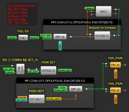
Figure 14. I2C control of duty cycle
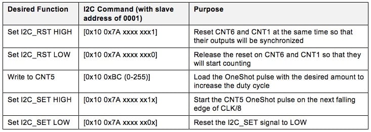
As shown in the red label in the image above, controlling the duty cycle over I2C requires the controller to perform a specific command sequence. These commands are shown in order in the table below. An "x" indicates a bit that the user should not change, "[" indicates a START bit, and "]" indicates a STOP bit.
Table 1. I2C Commands
The PDLY block generates a short active high pulse on the falling edge of the CLK/8 signal, which we call !CLK/8. That signal is used to clock DFF14 at a steady frequency. When I2C_SET goes high asynchronously, the next rising edge of !CLK/8 will cause DFF14 to output HIGH, which will trigger the CNT5 OneShot. The OneShot will run for the number of clock cycles that the user wrote as specified in the "Write to CNT5" I2C command in the table above. In this case, it is 10 clock cycles. The OneShot allows the 25MHz oscillator to run for exactly its duration and no longer so that 3-bit LUT0 receives the number of clock cycles that were written to CNT5 by the user.
The image below shows these signals, where the red clocks are the ones that are sent to 3-bit LUT0, which passes them into CNT6 (the PWM_SET counter), thus creating our offset for the duty cycle generation.
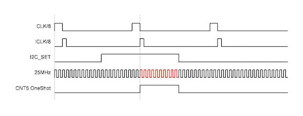
Figure 15. Loading the duty cycle with I2C (frequencies are not to scale)
Tachometer Reading
If desired, the user can read the tachometer value over I2C to track how quickly the fan is turning by reading the CNT2 value. CNT2 will be incremented every time ACMP0H has a rising edge, and can be asynchronously reset with an I2C command. (Note that this is an optional feature, and the threshold of ACMP0H will need to be tweaked according to the specs of the particular fan that is being used.)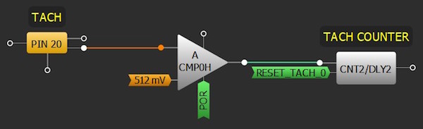
Figure 16. Tachometer section
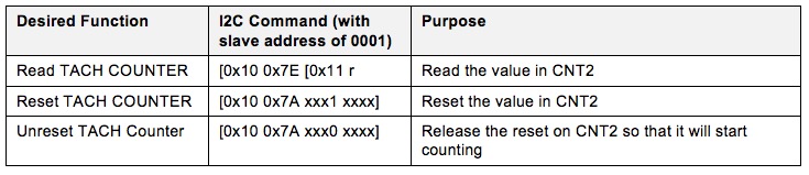
Table 2. I2C Commands
External Circuit Design
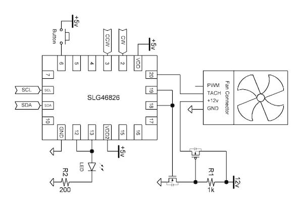
Figure 17. Fan Controller Block Diagram
The external circuit is fairly simple. There is a pushbutton connected to Pin6 of the GreenPAK to toggle whether this particular device is selected for rotary control, and an LED connected to Pin12 and Pin13 to indicate when the device is selected.
Since the fan runs off of 12 v, we need a pair of FETs to control its switching. The GreenPAK's Pin18 and Pin19 drive an nFET. When the nFET is turned on, it pulls the gate of the pFET LOW, which connects the fan to +12 V. When the nFET is turned off, the gate of the PFET is pulled up by the 1 k resistor, which disconnects the fan from +12 v.
PCD Design
We put together a couple of PCBs to prototype our design. The PCB on the left is the "Fan Controller," which houses the rotary encoder, 12 v jack, SLG46108 GreenPAK, and connectors for the FT232H USB to I2C breakout board. The two PCBs on the right are "Fan Boards," which contain the SLG46826 GreenPAKs, pushbuttons, switches, LEDs, and fan headers.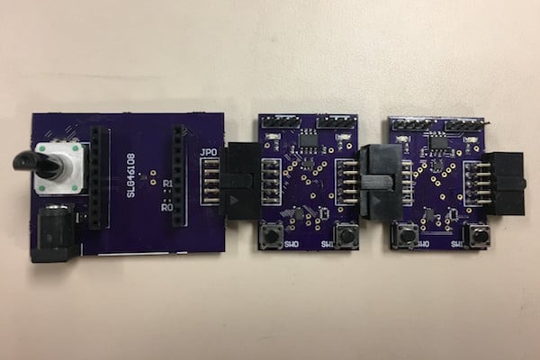
Figure 18. PCBs and connectors
Each Fan Board has a shrouded male header on the left side and a female header on the right side so that they can be daisy-chained together. Each Fan Board can be populated with resources to independently control 2 fans.
C# Application
We wrote a C# application to interface with our fan boards through the FT232H USB-I2C bridge. This application can be used to adjust the frequency of each fan with I2C commands that are generated by the application.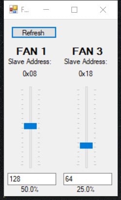
Figure 19. C# application GUI
The application will ping all 16 I2C addresses once per second and populate the GUI with the slave addresses that are present. In this case, we have Fan 1 (slave address 0001) and Fan 3 (slave address 0011) connected to the board. The user can adjust the duty cycle of each fan individually by moving the slider bar or by typing in a value from 0-256 in the textbox underneath the slider bar.
Project Conclusions
In this article, we created a fully-featured 12 v PC fan PWM controller with some Dialog GreenPAK configurable mixed-signal IC's. With our design, we are able to independently control up to 16 fans (since there are 16 possible I2C slave addresses) either with a rotary encoder or with a C# application. We demonstrated how to generate a PWM signal with a pair of offset counters, and how to increase and decrease the duty cycle of that signal without rollover.References
For related documents and software, please visit GreenPAK's product page.
Download the free GreenPAK Designer software [1] to open the .gp files [2] and view the proposed circuit design. Use the GreenPAK development tools [3] to freeze the design into your own customized IC. Dialog Semiconductor provides a complete library of application notes [4] featuring design examples as well as explanations of features and blocks within the Dialog IC.
[1] GreenPAK Designer Software, Software Download and User Guide, Dialog Semiconductor
[2] AN-CM-xxx PWM Control for PC Fans.gp (zip file), GreenPAK Design File, Dialog Semiconductor
[3] GreenPAK Development Tools, GreenPAK Development Tools Webpage, Dialog Semiconductor
[4] GreenPAK Application Notes, GreenPAK Application Notes Webpage, Dialog Semiconductor
[5] SLG46108 product page, Dialog Semiconductor
[6] SLG46826 product page, Dialog Semiconductor
[7] AN-1101 Unclocked Quadrature Decoder, Dialog Semiconductor
[8] DMP3085LSD-13DICT-ND, Diodes Incorporated
[9] QS5K2CT-ND, ROHM Semiconductor


No comments:
Post a Comment