Get the breakdown on a new Bosch
IMU designed for robotics and drone operation and learn a bit about
drone design considerations along the way.
This ruggedized sensor is designed for harsh-environment drone and robotics applications. It remains stable over a large temperature range and is able to tolerate high-vibration environments.
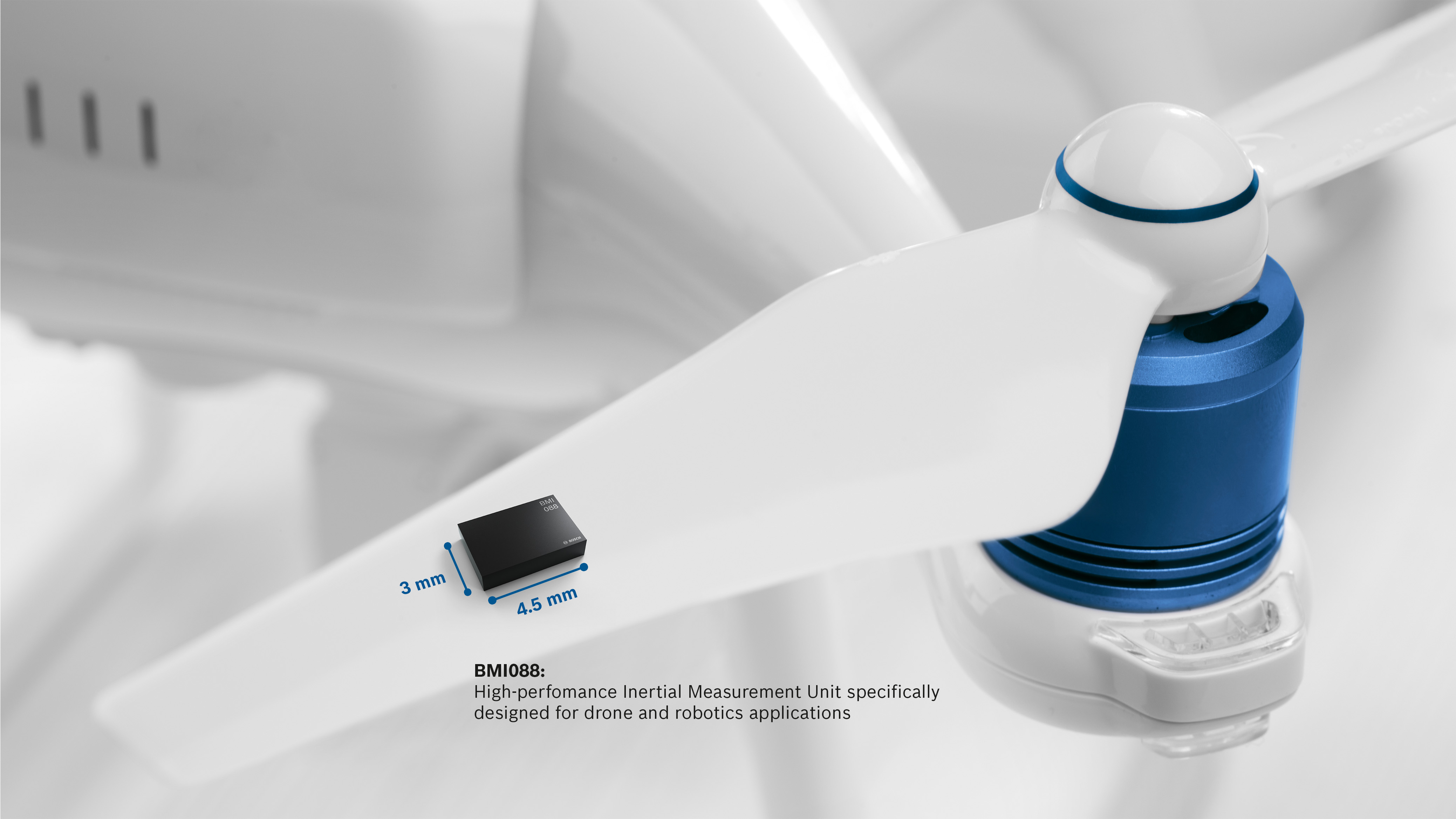
Picture of the sensor on fan blade provided by Bosch
The datasheet indicates that the sensor “provides accurate and reliable inertial sensor data” even when exposed to thermal variations and various forms of mechanical stress.
Specifications
The device offers multiple acceleration ranges (±3 g, ±6 g, ±12 g, ±24 g, where ) and multiple gyroscopic slew rates (±125°/s, ±250°/s, ±500°/s, ±1000°/s, ±2000°/s). Lower measurement ranges have corresponding higher sensitivity.The bias stability is attractive: the maximum bias drift is 2°/hr. This is an unusually low amount of drift for a consumer-grade gyroscope. Bosch might have found a way to economically incorporate a vibrating ring MEMs gyroscope in this package—otherwise, I cannot account for this level of stability. If you know more about the gyroscope used in this device, please let me know in the comment section below.
The device comes factory calibrated; however, you can expect a lifetime zero offset drift of up to ±30 mg (for the accelerometer) and ±1°/s (for the gyroscope). A zero offset is a number added to a raw sensor value that ensures that a zero reading corresponds to zero acceleration/rotation. Zero offset drift describes how the zero offset shifts over time.
The temperature coefficient offset (TCO) of the gyroscope is less than
. The accelerometer TCO is
Inside the IC
The BMI088 has a three-axis accelerometer and a three-axis gyroscope that feed data into analog-to-digital converters and then digital filters before providing it on either the SPI or the I2C interface.Additionally, two interrupts are available for each sensor to notify a host microcontroller of a data-ready condition.
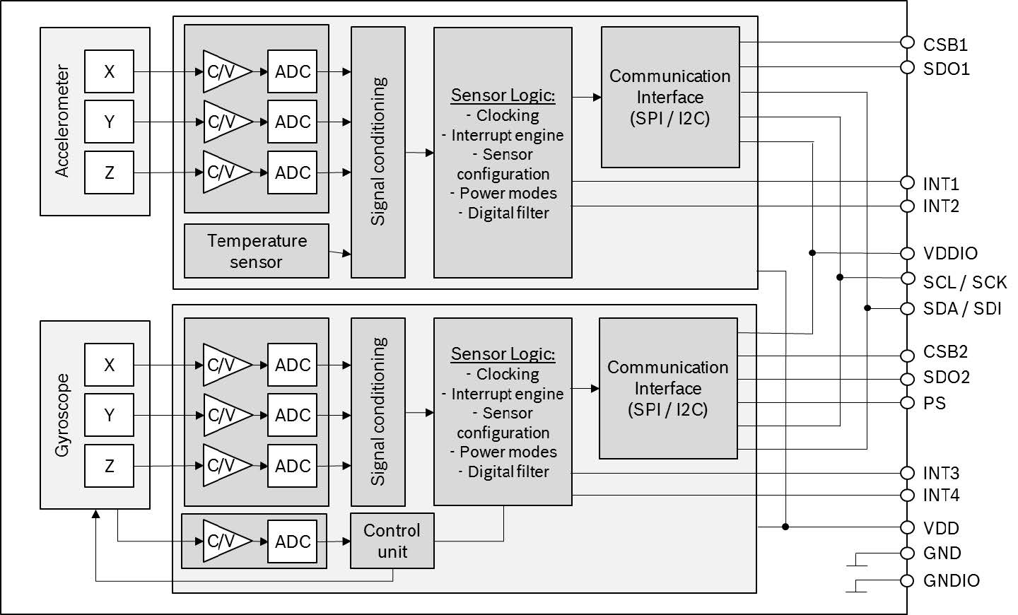
BMI088 Block diagram from the datasheet
Mounting
Whenever you mount a high-precision MEMS accelerometer or gyroscope sensor, you should always find, read, and understand the information related to handling, soldering, and mounting. It’s also a good idea to make friends with a mechanical engineer who has experience in the field.Electrical engineers typically don’t have much expertise in mechanical details such as how PCB design affects MEMS sensor performance. For example, if you have a hovering drone, the rotors will be rotating at a fixed frequency. The rotation can cause vibration on your PCB and may even lead to mechanical resonance.
Do you have any idea how that fixed-frequency vibration will affect the sensor? Do you know the rotation rate of your propellers and how that will affect the vibrational frequency of your machine? The number and placement of mount points, the thickness of the PCB, the properties of the substrate, and the location of the sensor on the PCB all affect the performance.
Thermal expansion of the PCB, mechanical stresses caused by proximity to mount points, the number of mount points, and how tightly the screws attach the PCB to the mount points all affect the sensor in one way or another. A qualified mechanical engineer can advise you on how to best protect your sensor from these noise sources and mechanical difficulties. They can also analyze your PCB design for issues that you may not even begin to think about.
Below is a 1-inch by 1-inch plate secured at all four corners (the left-hand animation) and at only three corners (the right-hand animation). The simulation exposes the plate to a variety of frequencies until resonance occurs. At a resonant point, the plate bends and flexes the maximum amount. If your sensor is mounted at a point colored in red, it will experience significant vibration and oscillation—possibly damaging the sensor, and definitely disrupting the measurements. The color gradients below represent minimum displacement (blue) and maximum displacement (red).
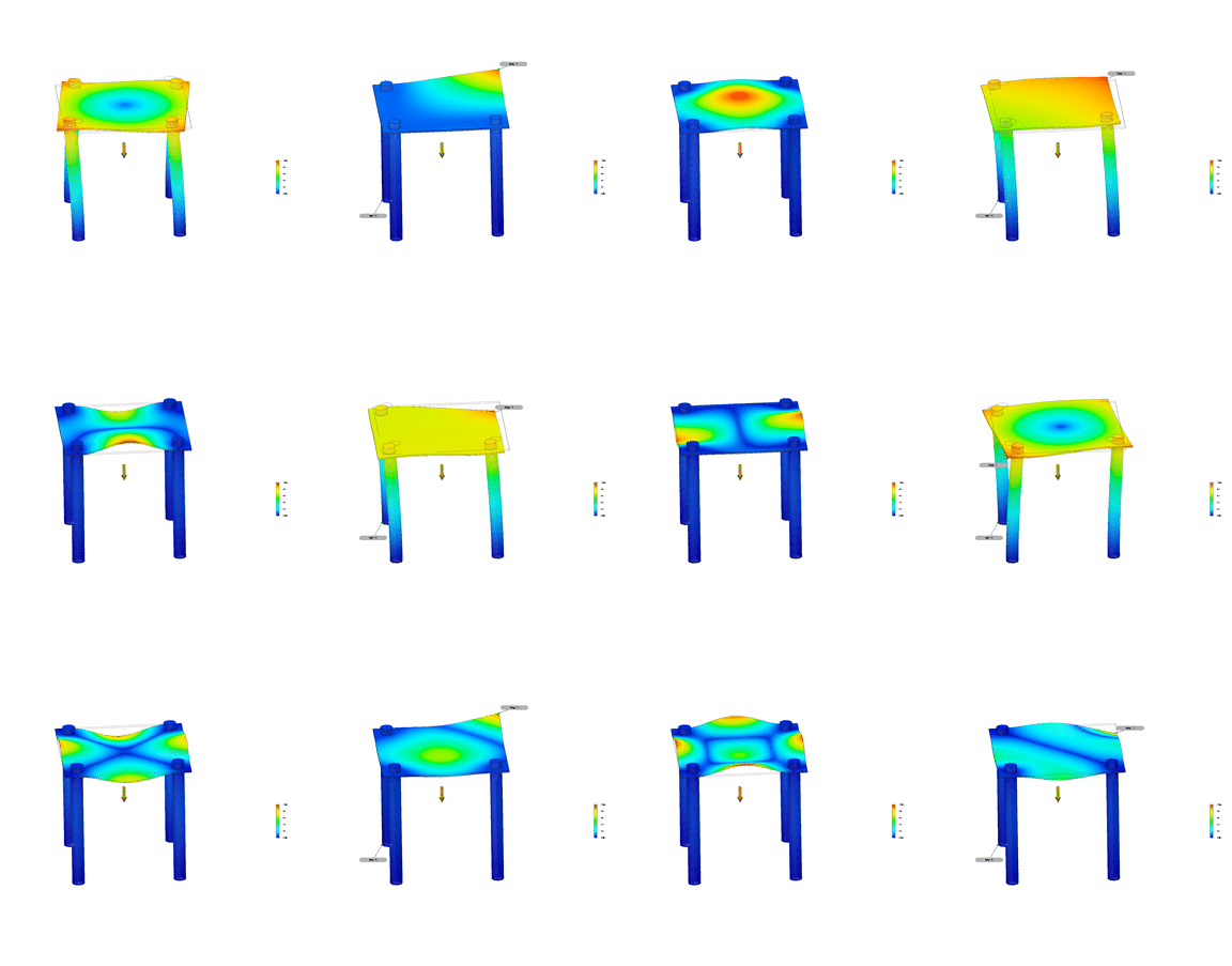
Autodesk Fusion modal analysis of a 1-inch by 1-inch plate (to represent a PCB mounted at 3 and 4 locations). Red indicates maximum displacement and blue represents minimum displacement at a given frequency.
Bosch recommends that you keep the sensor away from mechanical stress points, heat sources, and epoxy-covered sensors (because the epoxy might partially cover the BMI088, which in turn could lead to mechanical stress. They also recommend not mounting the sensor at the center of four mount points because the vibration will be more severe, as indicated in the animation shown above.
Reflow Soldering
How often do you pay attention to the reflow process during manufacture? Or to put it another way—have you ever paid attention to the reflow process during manufacture? Electrical engineers work in an incredibly complicated field. The smallest of mistakes or oversights can cripple our designs. With a growing number of prototypes being made in home shops or with repurposed toaster ovens, the opportunity for errors grows by the day.Bosch’s “Handling, Soldering and Mounting Instructions” document indicates that this IC can be reflowed up to three times before permanent damage occurs. It also states that the device must be between 217°C and 260°C for 60-150 seconds and within 5°C of 260°C for 20-40 seconds.
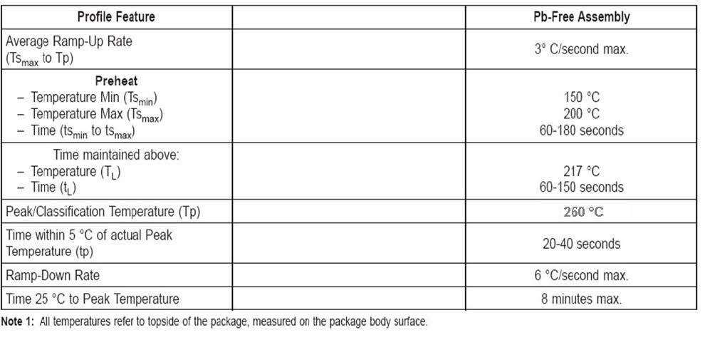
Reflow guidelines for lead-free assembly from Bosch IMU Handling, Soldering, and Mounting Instructions
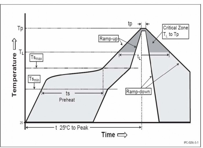
Reflow solder graph from Bosch IMU handling, soldering, and mounting instructions
Other devices on the same PCB might have different reflow profiles—this is usually the result of different package sizes or the difference between lead and lead-free solder profiles (which are usually incompatible).
The moral of the story is to know everything you can about your components before you select them for your design. What you don’t know can hurt you.
Using the Data
The device conveniently supports SPI and I2C data transfer. Data is stored in FIFO memory, and data-ready interrupt signals for the gyroscope and the accelerometer can be mapped to output pins.Once you offload the data to your host microcontroller, you’ll need to do something with it. In my limited experience, the two most popular ways to filter the data are the Kalman filter and the complementary filter.
You might also be interested in Bosch’s Sensor Fusion Software—it can output orientation in Euler angles or quaternions.
Conclusion
IMUs are fun to play with and incredibly useful. As the technology continues to improve, we will see more devices that use accelerometer and gyroscope information to accurately locate objects indoors with an accuracy that rivals or exceeds GPS.If you have used a similar sensor in your projects, please tell us about it in the comments below—or better yet, link to your project in the forums!


No comments:
Post a Comment