


A modern high-quality audio system
has excellent specifications and sounds almost perfect. Almost perfect,
but not quite. There is one very important attribute missing in audio
systems—the attribute we call “presence”. This article discusses an
alternative power amplifier design with sound that often lacks in
conventional amplifiers.
As listeners, even as audiophile listeners, we don’t fuss about this lack of presence because we have come to accept that what we hear from a modern audio system is as good as it gets. Yet this just isn’t true, and it doesn’t have to be accepted.
The lack of presence occurs almost entirely as a result of distortions inherent in the fundamental design of all commercial power amplifiers. Have you noticed how much clearer headphones sound? It's due to the fact that they are driven by low-powered amplifiers.
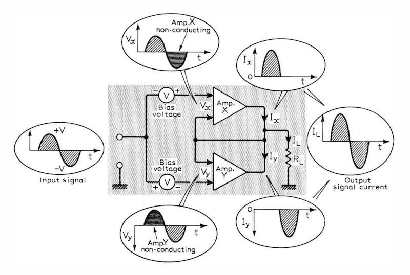
"Block diagram of conventional class B amplifier with the two halves of a complementary output stage represented by sub-amplifiers X and Y. " From Peter Blomley's 1971 article (PDF).
In this article, I demonstrate that there is an alternative power amplifier design that suffers virtually no distortion, and provides a sound which has the presence so lacking in conventional amplifiers. This amplifier was designed over forty years ago, and yet despite its superb fidelity, it has never seen commercial production.
I will introduce the idea of “rogue frequencies” and their effect on our listening experience. I will then go on to show how this original and truly suburb amplifier successfully minimizes distortions and does not generate disturbing rogue frequencies.
This design is so effective and the output so pure that it creates an audio presence that is quite impossible to ignore.
To understand why commercial amplifiers produce a sound which is very good but which lacks presence, I will begin by discussing the sensitivity of the human ear. Then I will examine types of distortion and how these affect what we actually hear.
Finally, as a potential add-on to the original design, I will discuss distortion caused by “clipping” and how to reduce its harshness.
A Brief Anecdote about a Gramophone
Recently, I went to visit an enthusiast friend who wanted to show me a genuine 1890’s wind-up gramophone with a real thorn needle and a real “His Master’s Voice” horn that he had just bought.
His Master's Voice, painted 1898 by Francis Baurraud.
With the purchase of the gramophone came some very old 78rpm records made directly from the original wax master—the huge horn of the recording gramophone was placed close to the orchestra and the needle cut a spiral groove, using only sound energy, in a platter covered with a thin layer of wax. There was an original record in good condition of Caruso in full glorious voice! There were also some orchestral and choir records.
These were all made before the triode was invented so no electronics were used in their manufacture. To humor my friend I agreed to listen, expecting an unpleasantly distorted sound. As I suspected, there was hiss and there were crackles, but the music! Pure and clear, you could hear each and every instrument and voice completely separately and beautifully, even with a choir and a mono recording source. Caruso really does deserve his reputation. It sounded ALIVE and PRESENT, even though it was made in 1902.
So why do modern amplifiers, with all the remarkable improvements we have achieved in electronic technology, lack this essential quality of presence?
How the Human Ear Perceives Harmonic Distortion
The human ear is extraordinarily sensitive. Under ideal conditions, the ear can hear sounds from the eardrum moving by as little as the diameter of a hydrogen atom (~10-10 m). Curiously, while the human ear can be very sensitive to some things, it isn't very sensitive to other things. For example, to notice a change in volume, the power has to be doubled (3db).So if you were to increase, say, the 2nd harmonic by 5%, it would be an extraordinary person who noticed. Thus, genuine pure harmonic distortion below about 10% is pretty undetectable and irrelevant for even the best hi-fi. However, harmonic distortion is easy for the engineer to measure to great levels of accuracy and down to very low levels—so it gets talked about a lot, even though it really doesn’t matter much in the long run!
Consider how you identify your mother’s voice instantly, even over the lo-fi telephone. It's done by harmonic content, and the human ear is very deeply tuned to harmonic content: "Have you got a cold, Mum!?" can be asked after just one sentence from her.
This shows us the introduction of extra harmonics is very audible indeed (as little as 0.01% is easily detectable as a different type of sound).
Intermodulation Distortion
Any two frequencies passed through a non-linear amplifier will produce the sum frequency and the difference frequency in addition to the original frequencies. The amplitude of these additional frequencies (“rogue frequencies”) is related to the amount of non-linearity. This is intermodulation distortion and it is very difficult to measure, especially at the extremely low levels that still remain significant to the human ear. These additional unwanted rogue frequencies are off-key on our standard musical scale, and even tiny amounts make the music sound “muddy”.
Music or voice consists of hundreds of superimposed frequencies at any given moment (as described by the mathematician Joseph Fourier). As this collection of frequencies is passed through an amplifier, additional small-amplitude "rogue frequencies" are added to the original signal, and the human ear is very sensitive to this additional frequency content, and immediately identifies that the sound is not real. This is a significant reason why you never confuse, say, voices on the TV or radio with real visitors even when you are in another room.
Even very good conventional amplifiers are not mistaken for the real thing! Transducers (such as a needle on a record or a loudspeaker) are usually reasonably linear (certainly the audiophile versions) so they do not introduce many rogue frequencies although their harmonic distortion (through resonances, etc.) can be quite large. The weakness in a hi-fi system, no matter its numerically apparent superb specifications, is usually only the amplifier.
Crossover Distortion
Amplifier analysis shows that a Class B amplifier has a no-feedback distortion of about 33% and a Class A amplifier has a no-feedback distortion of about 8% and sound better than Class B. Most of the Class B distortion comes from the use of the output transistors as rectifiers to separate the plus and minus halves of the signal as well as then amplifying those halves separately thereafter (“push-pull”).When a power transistor is driven below a collector current of about 15mA the amplification falls dramatically. If one could prevent the current in the output power-transistors from ever going below about 15mA and into this non-linear region, it would considerably improve things. This change of amplification causes the crossover distortion characteristic of class-B amplifiers.
Note that this crossover distortion should not be confused with the audio distortion, often also referred to as crossover distortion, which arises when audio signals are separated into frequency bands, as in loudspeaker circuits to feed the appropriate frequency range to each discrete driver unit.
Transient Intermodulation Distortion
Modern amplifier distortion is controlled by negative feedback, which reduces the distortion in proportion to the feedback. Amplification is cheaply available so the apparent non-linearity can be reduced to arbitrarily low levels by sufficient feedback.But the feedback signal takes time to get through the amplifier and back to the input negatively to quash the distortion. So when sudden changes (transients) occur there is a period during which the naked amplifier is exposed to the world, and the non-linearity adds intermodulation rogue signals to the original, which are not entirely canceled by the feedback. This is transient intermodulation distortion. What you need is an amplifier sensibly without distortion before applying feedback The distortion of a naked class-B amplifier is so bad that most analysis seems to only consider the with-feedback distortion.
One of the reasons that modern amplifiers sound better than their older counterparts (using essentially the same class A or B circuits as always) is the increase in speed of the components. Multi-gigahertz discrete components are freely available, and even cheap power transistors have an ft of many MHz. This means that the feedback time is now very short indeed.
Clipping Distortion and How to Soften It
Transistor amplifiers driven into saturation sound horrible because the tops of the waveform are very sharply clipped off, leading to square corners and a huge explosion of unpleasant harmonics. I find myself waiting to wince when a conventional amplifier is driven hard.On the other hand, near their clipping point, valves have quite a soft non-linear characteristic, resulting in a rounded squashed sine-wave which contain fewer spurious harmonics and sounds much better than the square-clipped sine-wave of a transistor amplifier driven hard.
A simple circuit invented by Carl F Wheatley, Jr. (US Patent 3 786 364 / 1974) uses a single transistor and three resistors (TRP and RP1, RP2 and RP3) for each output transistor (see below).

The complete Blomley Amplifier with complementary output and clipping protection. Click to enlarge.
It measures the combination of voltage (RP3) and current (= voltage across RP2) in the output transistors and when the combination of these two voltages exceeds about 0.6V BE it turns on TRP and removes the drive to the outputs.
Note that the 0.6V is nominal and some current starts to flow when Vbe exceeds ~0.45V so this is a “soft” turn-off. It has two advantages:
- It makes the amplifier “clip” softly, very similar to valve designs, which makes the sound very forgiving and prevents the “cringes”.
- It protects the output transistors from most abuse.
Peter Blomley's New Approach to Class B Amplifier Design
In the February and March 1971 editions of Wireless World, Peter Blomley published the revolutionary and very densely concentrated article “New Approach to Class B Amplifier Design” (PDF) in two parts (patented by Plessey, No.53916.69, though this patent has long expired).The very clever bit of the amplifier he describes is that Blomley split the incoming signal into top and bottom halves before applying the separate signals to the output transistors. Then he was easily able to design the output transistors to work only in their linear region (above a collector current of ~15mA).
Additionally, he made the observation that with voltage signals, diodes are very non-linear, but if you use a current source, the diode is so close to the theoretical ideal that one can really call it perfect (109 difference between forward and backward current in cheap diodes).
As shown in the schematic above, he used a constant-current source (Tr6) and had a varying current sink (Tr3). The current-difference drives diodes, which are actually transistors used as diodes, (Tr4 & Tr5) to rectify the current. By using very high-frequency transistors here the transition from the “top” signal to the “bottom” signal was so fast that it was way beyond 100kHz.

"New approach to class B amplifier in which SUb-amplifiers are biased above non-linear region and fed with uni-directional signals produced by the diodes. This effectively transfers signal splitting from the sub-amplifiers to a separate part of the circuit." From Peter Blomley (PDF).
After a little feedback is applied, there is unmeasurable intermodulation distortion, transient intermodulation distortion, and harmonic distortion. The resultant output of this amplifier is so clear that a recorded voice can easily be mistaken for a live person. Peter Blomley’s amplifier is a Class B amplifier with much better than Class A performance.
And yet Peter Blomley and his amplifier have gone virtually unrecognized in the audio world for more than 40 years. I suggest two reasons for this. First, his design was so original and so unexpected that few people understood it or took it seriously. Second, Blomley never put his design into commercial production because Plessey held the patent, so even fewer people were able to listen to it or review its performance.
Most of the audio hobbyists who constructed their own Blomley amplifier modified the design and in doing so introduced distortions. I suggest you build the original design (with perhaps just the minor modifications afforded by modern components) and listen to it. This will give you a reference sound to check any further modifications with which you might like to experiment.
Unfortunately, in ignoring the Blomley design for so long, the audio world has deprived itself of a fundamentally better amplifier. We have instead put all our efforts over the last forty years in trying to mitigate what we thought were unavoidable inherent characteristics of electronic amplifiers, particularly Class B amplifiers. The boldness of Peter Blomley as a young engineer was to question how unavoidable these characteristics really were, and to then set about designing them out of his amplifier.
Today, superb high-voltage, high-speed transistors are available which makes the Blomley amplifier even better than his 1971 version.
The original amplifier design was for a 30W amplifier with a 60V power-rail, and because of the purity, this is more than adequate for normal home use. In 1971, 100V small-signal transistors were rare, but this is no longer so and an 80V power-rail can now be used, with different transistors, increasing the power to 50W. However, high sound volumes are not needed as the sound is so exceptionally clean. The huge headroom provided with most amplifiers is there so you can play them at high volume and bury the crossover-caused intermodulation distortion in the high sound-level (quite sad really).
Conclusion
40 years ago I fell in love with the clarity and purity of the sound from the Blomley amplifier, but it took a long time to understand the circuit and to appreciate the brilliance of Peter Blomley. Now, I have built several of these amplifiers and, provided I stick to the original Blomley design, they all sounded better than superb.Human response, including our own, is often difficult to explain, but I have found that with a Blomley amplifier ordinary people find themselves wanting to listen to music much more than they do with a conventional top-end amplifier design. They don’t understand why, they just end up listening to more music, more often—surely the ultimate test. Listening to a Blomley amplifier is addictive. I have certainly found it so, as have many others fortunate enough to have experienced this extraordinary amplifier.
In fact, it is difficult to use it for background music; people tend to stop talking and start listening to the music. Its presence is compelling.
In his article, Peter Blomley expressed the very 1970s thought that states “The performance of an amplifier of this caliber is, in my opinion, wasted in a conventional audio set-up.” I built my first Blomley, and immediately realized that I could not agree with the sentiment he had expressed. My mother, who was garrulous in the extreme, sat through the whole of the “Pirates of Penzance” without saying a word! That was the 1970s and the other components in an audio system have come a long way since then.
The choice of a Blomley amplifier is now certainly warranted and is the best way to benefit fully from the technical advances made in all the other components of an audio system.
Notes on the Circuit
In most of the amplifiers I have built I have used a quasi-complementary output transistor arrangement but nowadays matched complementary power transistors are easily available. It really doesn't seem to matter!Great care must be taken to physically separate the input from the output to prevent high-frequency feedback. This amplifier is quick enough to use at RF frequencies.
I have the LTSpice file if anyone is interested in playing with it.
References
- “New Approach to Class B Amplifier Design” by Peter Blomley in Wireless World February and March 1971
- “The theory of transient intermodulation distortion” by Otala, Matti and Leinonen, Eero in Acoustics, Speech and Signal Processing, IEEE Transactions on (Feb 1977)
- “A Method for Measuring Transient Intermodulation Distortion (TIM)” by Eero Leinonen, Matti Otala, and John Curl in Journal of the Audio Engineering Society Volume 25 Issue 4 pp. 170-177; April 1977
- “Build a Low TIM Amplifier” by W Marshall Leach in Audio, Feb 1976


No comments:
Post a Comment