


This article defines VHDL
components, describes component declaration, and gives examples of how
to use VHDL components in your code. It also touches on the
"for-generate" statement and its uses.
This article will discuss use of VHDL components. Components allow us to break a large design into smaller and more manageable parts. Moreover, if we use this capability the code will be more readable. Also, we’ll look at the “for-generate” statement, which can sometimes dramatically simplify the code.
To discuss the advantages of using VHDL components, let’s consider writing the VHDL code for a four-bit adder.
The Schematic of a Four-Bit Adder
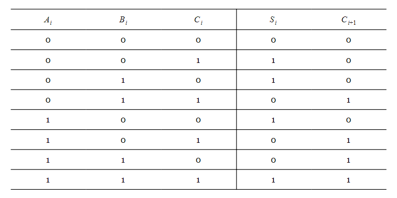
To add two n-bit numbers, we add the digits of each bit position together from right to left. This gives us a sum and a carry for each bit position. The carry produced in each column must be added to the digits of the next bit position. This means that binary addition requires a circuit that can add three bits.This circuit, called a full adder (FA), has the following truth table:
Here,
and
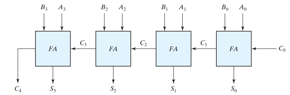
Figure 1. The block diagram of a four-bitbinary adder. Image courtesy of Digital Design.
VHDL Description of a Full Adder and a Four-Bit Adder
Based on the truth table of a full adder, we get the following expressions:So the VHDL code of a full adder is:
Listing 1
                    1 library IEEE;
2 use IEEE.STD_LOGIC_1164.ALL;

3 entity FA is
4  port(a, b, c_in : in std_logic;
5       s, c_out : out std_logic);
6 end FA;

7 architecture Behavioral of FA is
8 begin

9  s <= a xor b xor c_in;
10  c_out <= ( (a xor b) and c_in ) or (a and b);

11 end Behavioral;
a and b are the digits of the ith column and c_in is the input carry of the full adder. Adding these three bits gives a sum, s, and a carry, c_out. An ISE simulation for this code is shown in Figure 2.
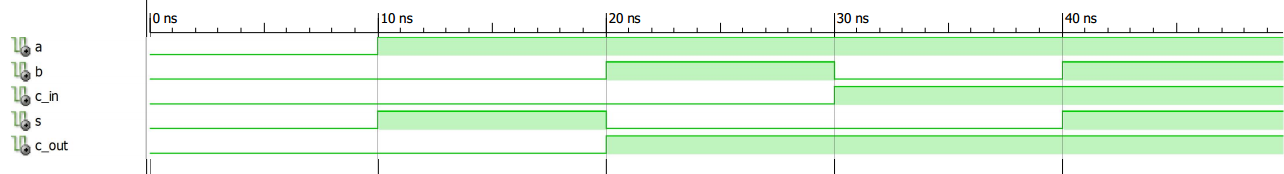
Figure 2
We can repeat Lines 9 and 10 to extend the VHDL code of a full adder into the VHDL code of a four-bit adder:
Listing 2
                    1 library IEEE;
2 use IEEE.STD_LOGIC_1164.ALL;

3 entity Four_Bit_Adder is
4     Port ( a : in  STD_LOGIC_VECTOR (3 downto 0);
5            b : in  STD_LOGIC_VECTOR (3 downto 0);
6            c0 : in  STD_LOGIC;
7            s : out  STD_LOGIC_VECTOR (3 downto 0);
 8            c4 : out  STD_LOGIC);
9 end Four_Bit_Adder;

10 architecture Behavioral of Four_Bit_Adder is

11  signal c3, c2, c1: std_logic;
12 begin

13  -- The first full adder
14  s(0) <= a(0) xor b(0) xor c0;
15  c1 <= ( (a(0) xor b(0)) and c0 ) or (a(0) and b(0));

16  -- The second full adder
17  s(1) <= a(1) xor b(1) xor c1;
18  c2 <= ( (a(1) xor b(1)) and c1 ) or (a(1) and b(1));

19  -- The third full adder
20  s(2) <= a(2) xor b(2) xor c2;
21  c3 <= ( (a(2) xor b(2)) and c2 ) or (a(2) and b(2));

22  -- The fourth full adder
23  s(3) <= a(3) xor b(3) xor c3;
24  c4 <= ( (a(3) xor b(3)) and c3 ) or (a(3) and b(3));

25 end Behavioral;
An ISE simulation for this code is shown in Figure 3.
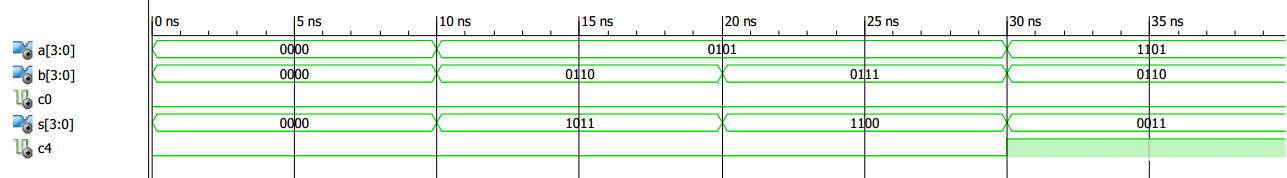
Figure 3
However, there is an alternative approach that can lead to cleaner code. In this case, we define a full adder as a sub-circuit and use it four times in our code. The VHDL lexicon uses the word “component” instead of “sub-circuit”.
Using VHDL Components
Component Declaration
To use the full adder block as a component in our code, we can save the code of Listing 1 as a separate file, namely FA.vhd, in our project.Now, we need to specify that the circuit described by FA.vhd is a component in our main code. This is called component declaration. To declare the FA component in our main code, we need to add the following lines:
                    component FA is
 port(a, b, c_in : in std_logic;
      s, c_out : out std_logic);
end component;
This tells the synthesis software that FA is a component with three inputs (a, b, c_in) and two outputs (s, c_out). It also specifies the data type for these inputs and outputs.
As you can see, these pieces of information are exactly the same as those provided by the “entity” part of the VHDL description of the FA (lines 3 to 6 of Listing 1).
In essence, the component declaration describes the interface of a component with its environment (see Figure 4).
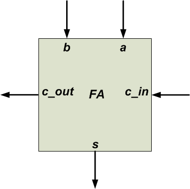
Figure 4
Component Instantiation
Now that the FA component is declared, we can use (or instantiate) it. Component instantiation specifies the interconnection of the component with other parts of the system.For example, consider the rightmost FA in Figure 1. In this case, as shown in Figure 5, A0, B0, C0, S0, and C1 of the top-level circuit should be connected to a, b, c_in, s, and c_out of the rightmost FA, respectively.
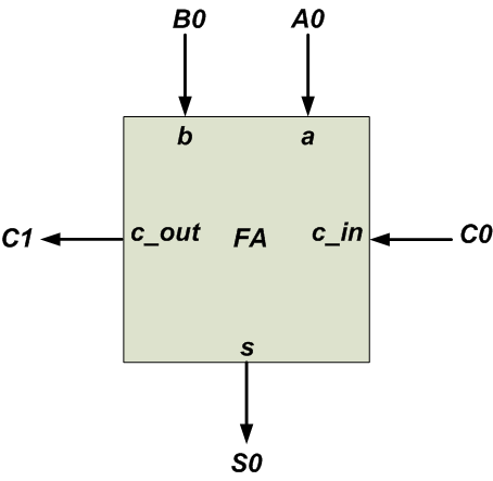
Figure 5
We use the “port map” statement to describe the interconnections of a component to the top-level circuit. For example:
u1: FA port map (a => A0, b => B0, c_in => C0, s => S0, c_out => C1);
Here, u1 is an arbitrary label for this component instantiation and FA specifies the component name. The notation a => A0 means that the a port of the FA component is connected to A0 from the main circuit. Similarly, we can use the following code to describe the leftmost FA in Figure 1.
u4: FA port map (a => A3, b => B3, c_in => C3, s => S3, c_out => C4);
We can write the VHDL description of the four-bit adder as follows:
Listing 3
                    1 library IEEE;
2 use IEEE.STD_LOGIC_1164.ALL;

3 entity Four_Bit_Adder is
4     Port ( a : in  STD_LOGIC_VECTOR (3 downto 0);
5            b : in  STD_LOGIC_VECTOR (3 downto 0);
6            cin : in  STD_LOGIC;
7            s : out  STD_LOGIC_VECTOR (3 downto 0);
8            cout : out  STD_LOGIC);
9 end Four_Bit_Adder;

10 architecture Behavioral of Four_Bit_Adder is

11  component FA is
12   port (a, b, c_in: in std_logic;
13             s, c_out: out std_logic);
14  end component;
15  signal c: std_logic_vector(4 downto 0);
16 begin

17  u1: FA port map (a => a(0), b => b(0), c_in => c(0), s => s(0), c_out => c(1));
18  u2: FA port map (a => a(1), b => b(1), c_in => c(1), s => s(1), c_out => c(2));
19  u3: FA port map (a => a(2), b => b(2), c_in => c(2), s => s(2), c_out => c(3));
20  u4: FA port map (a => a(3), b => b(3), c_in => c(3), s => s(3), c_out => c(4));
21  c(0) <= cin;
22  cout <= c(4);

23 end Behavioral;
Note that the component declaration comes in the “architecture” of “Four_Bit_Adder” before the “begin” keyword. An ISE simulation of the above code is shown in Figure 6.
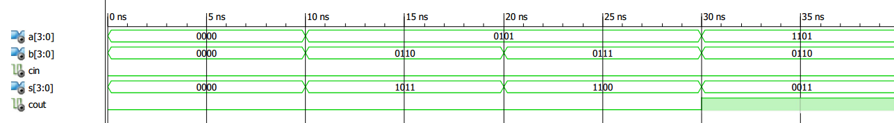
Figure 6
VHDL “For-Generate” Statement
The schematic described by lines 17-20 of Listing 3 is shown in Figure 7.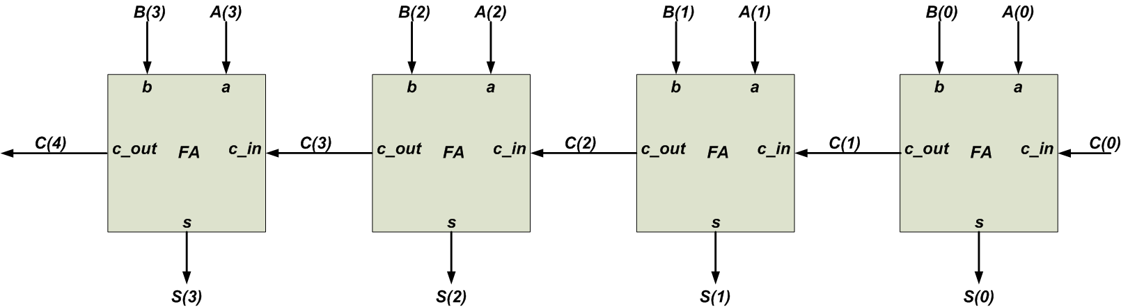
Figure 7
There is a certain pattern in this structure. By using an index, i, ranging from 0 to 3, we can describe all of these instantiations with a single statement:
uut: FA port map (a => a(i), b => b(i), c_in => c(i), s => s(i), c_out => c(i+1));
where i=0 gives the rightmost FA instantiation (line 17 of Listing 3), i=3 gives the leftmost FA instantiation (line 20 of Listing 3), and so on. To describe such repeated structures, VHDL allows us to use the “for-generate” statement. The “for-generate” statement that describes Figure 7 would be:
                    1 gen: for i in 0 to 3 generate
2  uut: FA port map (a => a(i), b => b(i), c_in => c(i), s => s(i), c_out => c(i+1));
3 end generate;
Here, gen is an arbitrary label for the “for-generate” statement, and i, which comes between the keywords for and in, is an identifier that specifies the number of repetitions of the statements inside the “for-generate” structure.
The range of i is from 0 to 3 in this example. This means that the statement of Line 2 will be executed four times with i=0, 1, 2, and 3. Since i takes the values 0 to 3, lines 17-20 of Listing 3 will be created. The following code uses the “for-generate” statement to implement a four-bit adder:
Listing 4
                    1 library IEEE;
2 use IEEE.STD_LOGIC_1164.ALL;

3 entity Four_Bit_Adder is
4     Port ( a : in  STD_LOGIC_VECTOR (3 downto 0);
5            b : in  STD_LOGIC_VECTOR (3 downto 0);
6            cin : in  STD_LOGIC;
7            s : out  STD_LOGIC_VECTOR (3 downto 0);
8            cout : out  STD_LOGIC);
9 end Four_Bit_Adder;

10 architecture Behavioral of Four_Bit_Adder is

11  component FA is
12   port (a, b, c_in: in std_logic;
13             s, c_out: out std_logic);
14  end component;
15  signal c: std_logic_vector(4 downto 0);
16 begin

17  gen: for i in 0 to 3 generate
18   uut: FA port map (a => a(i), b => b(i), c_in => c(i), s => s(i), c_out => c(i+1));
19  end generate;
20  c(0) <= cin;
21  cout <= c(4);

22 end Behavioral;
Conclusion
The use of VHDL components is a helpful technique, particularly when we need to implement the same functionality many times or when a subcircuit is complicated and has a lengthy VHDL description. Moreover, when the circuit has a pattern similar to that of Figure 7, we can use the “for-generate” statement to dramatically simplify the code.To understand the advantages of these VHDL statements, just imagine how unwieldy the code would be if we designed a 64-bit adder without using the component and “for-generate” statements!


No comments:
Post a Comment