


This article reviews the use of carry-save adders to efficiently compute a multioperand addition.
There are many circumstances in which we need to add a set of numbers together. For example, consider computing the inner product of two vectors of length n, and
Multioperand Addition Using a Two-Operand Adder
We can use a single two-operand adder sequentially to perform a multioperand addition. Assume that we need to add m numbers together, i.e.. Also, assume that the sum of these numbers, acc, can be represented by n bits. For this addition, we can use the block diagram of Figure 1.

Figure 1
At the beginning of the calculations, the n-bit register is reset to zero. Then, the first operand,
, is selected by the multiplexer and applied to the n-bit adder. The other input of the adder, b, comes from the n-bit register. Hence, at this stage, the output of the n-bit adder will be
Next, the second operand,
, will be chosen by the multiplexer. This will be added to the current value of the n-bit register which gives
Delay of Multioperand Addition Using a Two-Operand Adder
The structure of Figure 1 utilizes a single adder to perform multioperand addition, as a result, it is hardware efficient but it’s not efficient from delay point of view. Let’s examine the delay of this structure. The main time-consuming operation of the above procedure is the addition of two n-bit numbers. If we consider a delay offor the n-bit adder, then, the delay of adding m numbers can be roughly estimated as
There are a wide variety of configurations for implementing an n-bit adder, but to keep things simple, we assume that a simple ripple carry adder is utilized. The structure of a four-bit ripple carry adder is shown in Figure 2.
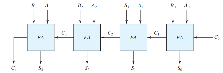
Figure 2. The block diagram of a four-bit ripple carry adder. Image courtesy of Digital Design.
In this figure, to calculate
and
We can speed up the calculations by employing other structures for the n-bit adder. For example, we may utilize a carry-lookahead structure, but these methods usually increase the complexity of the system significantly.
There’s an interesting method, namely carry-save adder, which can be used to efficiently implement a multioperand adder without increasing the utilized hardware significantly. In the next section of the article, we will review the reasons for the slow operation of the above structure, then, we’ll review the carry-save method.
The Reasons for Being Slow
How can we speed up the above multioperand addition?We need to pay attention to two points: first, the delay is proportional to the number of operands m. If we could somehow reduce the number of operands, we would be able to speed up the multioperand addition. For example, assume that we could manipulate the operands of a three-operand addition and reduce it to a two-operand addition. This would reduce m from three to two and would reduce the delay of multioperand addition by a factor of
.
Second, a ripple carry adder is slow because we cannot calculate the sum before calculating the carry signals of the previous bit positions. For example, in Figure 2, to calculate
and
Unfortunately, we cannot calculate the final sum without taking into account the carry signals of all the previous bit positions but we can reduce the number of operands without waiting for the calculations of other bit positions. We’ll explain this through an example:
Convert a Three-Operand Addition to a Two-Operand Addition
Consider adding three four-bit numbers (1011, 1101, and 0101) below: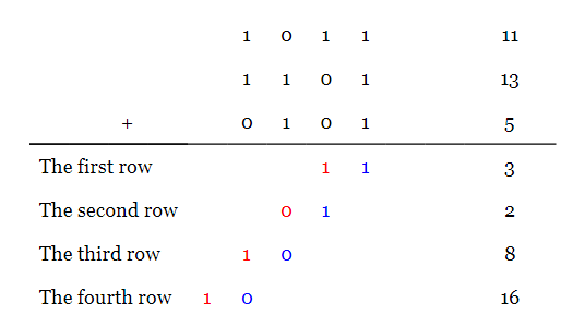
Adding the three bits from the first column, we have
. The conventional method of addition adds the produced carry to the digits of the next bit position. Here, we have simply written down the result of the first column in the first row of our calculations. The carry produced from this stage of calculations is shown in red under the second bit position.
Similarly, for the second bit position of the operands, we have
. These two bits are written in the second row of our calculations. Note that these two bits,
Now, note that there are only two bits in each column of our new representation (in other words, there can be at most two non-zero bits in each column). Hence, we can rearrange this addition and replace it with a two-operand addition as shown below:
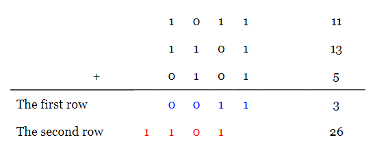
Here, the carry produced by each column is written under the next column in the second row of our calculations (the bits in red). The other bits are written in the first row in blue. As you see, the new representation gives the correct sum, i.e.
.
This example shows that we can efficiently reduce a three-operand addition to a two-operand addition. It should be noted that we worked on the bits of each column independently. In other words, we can use dedicate hardware to calculate the two-bit equivalent of different columns simultaneously. This is in contrast to the operation of a ripple carry adder which cannot calculate the sum before calculating the carry signals of the previous bit positions. Also note that a full adder is, in fact, the hardware that calculates the two-bit representation for the three bits of the columns. Working with l-bit numbers, we’ll need l full adders to convert a three-operand addition (
) to a two-operand addition (

Figure 3. An l-bit carry-save adder.
This circuit has similarities to the ripple carry adder of Figure 2; however, here, the carry is not propagated to the next bit position instead it is stored for the future calculations. That’s why the structure of Figure 3 is called a carry-save adder. All the FAs of a carry-save adder work in parallel. Also note that the index for the v signal, which stores the carry produced by different bit positions, starts from two, v(2), rather than one v(1). This can be understood from the numerical example above.
For the above numerical example, there are four columns and we’ll need four FAs to convert the three-operand addition to a two-operand addition. Since all of these FAs work in parallel, the delay of this conversion will be that of a single FA,
. Now, we can use a four-bit adder to perform the final two-operand addition. Hence, the overall delay will be
Convert a Multioperand Addition to a Two-Operand Addition
In the previous section, we saw that a carry-save adder can replace a three-operand addition,, with a two-operand addition,
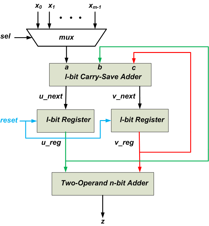
Figure 4
There are two l-bit registers which store the value of u_next and v_next signals calculated by the l-bit carry-save adder. The operands are applied to the carry-save adder one at a time through a multiplexer. The other inputs of the carry-save adder come from the l-bit u and v registers. At the beginning of the calculations, the l-bit registers are reset to zero. As a result, the above schematic actually calculates the sum
which is obviously equal to the desired sum
Then, the next operand,
, is selected by the multiplexer and applied to the l-bit carry-save adder. The other inputs of the carry-save adder, b and c, come from the l-bit registers which represent the sum
For more information, please read Chapter 8 of Computer Arithmetic: Algorithms and Hardware Designs and Chapter 7 of Guide to FPGA Implementation of Arithmetic Functions.
Summary
- There are many circumstances in which we need to add a set of numbers together.
- We can use a single two-operand adder sequentially to perform a multioperand addition. Such multioperand addition is hardware efficient but it’s not efficient from delay point of view.
- Working with l-bit numbers, we’ll need l full adders to convert a three-operand addition (
- ).
- By repeatedly applying the concept of carry-save adder, we can convert a multioperand addition to a two-operand addition.
To see a complete list of my articles, please visit this page.


No comments:
Post a Comment