


In this project, you'll learn how
to build a 4-bit binary counter using a 5x7 LED matrix for data count
value visualization. The project will use a combination of standard
electronic and surface mount components.
I decided to give a classic digital circuit a new twist by using a 5x7 LED matrix and littleBits' surface mount component (SMC) based electronic modules.
With this project, you will learn how to build a binary counter using a 5x7 LED matrix for a new output display appearance. You will learn how to wire a 5x7 LED matrix to display vertical bars that scroll from right to left based on a clock pulse and binary data numbers. Also, littleBits will illustrate how to quickly build new electronic circuits and devices using these unique SMC electronic modules.
Figure 1 shows the key circuit blocks for the 4-bit digital counter.

Figure 1. Block diagram for the 4-bit binary counter with 5x7 LED matrix.
The littleBits Pulse and Power Bits
To build a proper functioning 4-bit binary counter, a key electronic circuit required is a digital clock. The digital clock circuit provides a series of repetitive pulses, or square waves, for proper time sequencing of an electronic device. The 4-bit binary counter needs a digital clock to sequence the numerical data in the correct counting order. Instead of using a traditional digital clock circuit like a 555 timer, a littleBits pulse bit can be used as shown in Figure 2.
Figure 2: The littleBits pulse bit.
The pulse module uses SMC technology to make a small electronic circuit package. Investigating the design further, the pulse bit actually uses a 555 timer circuit. Figure 3 shows the electronic circuit schematic diagram for the littleBits pulse bit. The speed rate of the clock pulses can be adjusted using a small Phillips screwdriver.

Figure 3: The littleBits pulse bit uses a traditional 555 timer circuit.
To operate this circuit, a power bit is available. The power bit allows an ordinary 9V battery to provide a constant +5VDC supply voltage to the 555 timer circuit. The key circuit behind this DC-to-DC conversion is an LM1117 voltage regulator. The LM1117 is a low-cost SMC equivalent to a 7805 device.
The 7493 binary counter IC requires a +5VDC voltage supply for proper operation. The power bit module meets this voltage supply requirement in a small PCB (printed circuit board) package. The power bit is shown in Figure 4.

Figure 4: The littleBits power bit.
Here's the circuit schematic diagram of the power bit for additional reference:

Figure 5: The littleBits power bit (+5VDC voltage regulator) circuit schematic diagram.
Making the Power and Signal Connections: The littleBits Proto Module
The circuit combinations of the power bit and pulse bits provide both proper voltage supply and digital clock circuit requirements for the 4-bit binary counter project. In order to use these electrical signals with the discrete digital circuit, a special breakout interface board is needed. A littleBits component that easily achieves this interface requirement is a proto module as shown in Figure 6.
Figure 6: The littleBits proto module.
The secret behind the littleBits modules is the use of magnets and tiny male pins mounted on bitsnaps. The error in wiring an electrical-electronic device is eliminated by the magnets opposing incorrect module connections. Properly connected modules will be attached to each other by the magnets.
Figure 7 shows the three pins of gnd, signal, and vcc on each of the bitsnaps.

Figure 7: The proto module bitsnap pins and magnets.
The terminal blocks have tiny screws allowing wires to be inserted into small cavities for electrical connections to external circuits. All three pins will be used to power the 7493 4-bit binary counter as well as provide proper timing to increment the numerical count values. The arrangement of power, pulse bits, and proto modules are shown next:

Figure 8: The +5VDC power rail - pulse module device.
The optional mounting plate shown in Figure 9 can be used to provide a more sturdy structure for the snapped littleBits modules.

Figure 9: The mounting plate provides a solid structure for the littleBits +5VDC power rail-pulse module device.
The next building block to review is the 4-bit binary counter.
The 4Bit binary counter
The digital clock signal that is produced by the pulse module needs to be changed into binary data. An LED matrix can be used to display binary bits of 1s and 0s produced by an electronic counter. The sequence binary bit pattern represents decimal numbers ranging from 0 to 15. The magic behind an electronic counter is based on a cheat sheet called binary weighted values. The binary weighted values are based on base 2, using the simple exponent format of 2n. The following figure shows a 4-bit weighted value cheat sheet.
Figure 10: The weighted values cheat sheet using the exponent format of 2n.
The weighted values cheat can be expanded to show all 16 combinations of numbers produced by the binary counter. The 16 combinations of numbers are based on the quick calculation of 24. The exponent "4" is the counter's physical digital output.
Figures 11 and 12 show a basic block diagram of a 4-bit binary counter and a completed counting table.

Figure 11: A 4-bit binary counter with digital outputs being sequenced by the littleBits pulse module.
The 16 numbers produced by the 4Bit binary counter can be shown on a counting table.

Figure 12: The binary counter will count from 0 to 15 and recycle back to 0 based on this counting table.
For additional information on this counter and other types of digital sequential circuits, check out Chapter 11 of the All About Circuits Electronics textbook. Now, let's build a working 4-bit binary counter.
Building the 4-Bit Binary Counter
The electronic counting device requires a 4-bit binary counter to generate the digital data discussed in the last section. Although binary counters can be built using flip-flop circuits, you will build your device using a dedicated digital IC for this specific application.The 7493 digital IC is a 4-bit binary counter. It can count from 0 to 15 based on a digital clock applied to the appropriate input pin. The 7493 4-bit Binary Counter IC pinout is shown in Figure 13.

Figure 13: The 7493 4-bit binary counter IC with pinout.
Place the discrete electronic components on two solderless breadboards as shown in Figure 14. To accommodate the 5x7 LED matrix on a solderless breadboard, two of them are required for proper mounting of the optoelectronic display.

Figure 14: The complete 4-bit binary counter with 5x7 LED matrix device built on two solderless breadboards.
You can identify proper orientation of the 5x7 LED matrix by placing the component with the part number facing the four blue wires as shown in the wiring diagram. The 5x7 LED matrix is unique because each discrete light emitting diode is wired in a row-column fashion. All of the LED cathodes are wired together in each row and the anodes connected in their respective columns.
Figure 15 shows the internal wiring of the LED matrix.

Figure 15: The 5x7 LED matrix display along with the internal wiring diagram. Pin 1 is located on the left side of the displayed part number on the optoelectronic component.
With the electronic components placed on the two solderless breadboards, you can wire the circuit using jumper wires and preformed 24AWG (American Wire Gauge) solid wires as shown in Figure 14. Once the breadboard wiring is completed, the littleBits modules can be attached and wired to the correct solderless breadboard locations. As an additional wiring resource, I've included a circuit schematic diagram shown next.
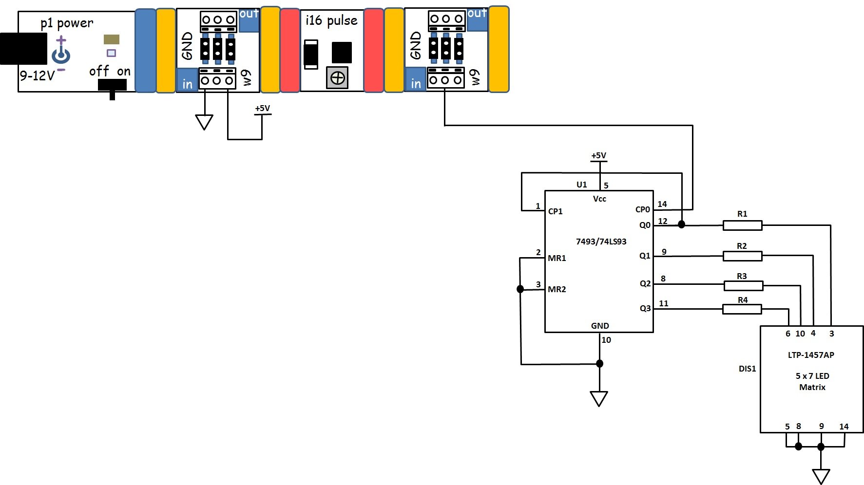
Figure 16: The circuit schematic diagram for the 4-bit binary counter with 5x7 LED matrix display.
The final binary counter device should look similar to Figure 17.

Figure 17: The author's completed 4-bit binary counter with 5x7 LED matrix.
Before applying voltage to your project, recheck and correct any wiring errors. If there are no wiring errors, apply voltage to your circuit by sliding the switch to the right on the power bit. The counter will display a series of counting bars. The counting sequence of 0 through 15 will repeat until voltage is removed from the circuit. I've included a video clip showing the counter in action provided below. Congratulations on building the 4-bit binary counter project. Happy counting!!!


No comments:
Post a Comment