


What are Voltage Multipliers?
Voltage multiplier refers to an
electrical circuit consisting of diodes and capacitors which multiplies
or increases voltage and also converts AC to DC, multiplying of voltage
and rectification of current is done using voltage multiplier.
Rectification of current from AC to DC is achieved by diode and
increase in voltage is achieved by acceleration of particles by
propelling high potential produced by capacitors.
Voltage Multiplier
A combination of diode and capacitor
makes basic voltage multiplier circuit; AC input is given to circuit
from a power source where rectification of current and particle
acceleration by capacitor gives an increased voltage DC output. Output
voltage can be many times higher to input voltage so load circuit must
possess high impedance.
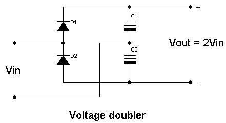
In this voltage doubler circuit the
first diode corrects the signal and its output is equivalent to the
peak-voltage from the transformer rectified as a half wave rectifier. An
AC sign by means of the capacitor additionally achieves the second
diode, and in perspective of the DC furnished by the capacitor this
makes the output from the second diode sit on top of the first. Along
these lines the output from the circuit is double the peak-voltage of
the transformer, less the diode drops.
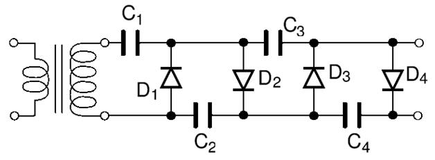
Varieties of circuit and idea are
accessible to furnish a voltage multiplier capacity of practically any
variable. Applying the same rule of sitting one rectifier on top of an
alternate and utilizing capacitive coupling empowers a type of step
system to advance.
Classification of Voltage Multiplier:
Classification of voltage multiplier is based on ratio of input voltage to output voltage accordingly names also been given as
- Voltage doublers
- Voltage Tripler
- Voltage quadruple
Voltage Doubler:
Voltage doubler circuit consists of two
diodes and two capacitors where each combination of diode-capacitor
circuit shares positive and negative alteration also connection of two
capacitors leads to double output voltage for a given input voltage.
Voltage Doubler
Similarly a each increase in a
combination of diode-capacitor multiplies input voltage where voltage
Tripler gives Vout = 3 Vin and voltage quadruple gives Vout = 4 Vin.
Calculation of Output Voltage
For a voltage multiplier output voltage
calculation is important considering voltage regulation and percentage
ripple is important.
Vout = (sqrt 2 xVin x N)
Where
Vout = output voltage of N stage voltage multiplier
N = no. of stages (it is no. of capacitor divided by 2).
Applications of Output Voltage
- Cathode Ray Tubes
- X-ray system, Lasers
- Ion pumps
- Electrostatic system
- Travelling wave tube
Example
Consider a scenario where 2.5 Kv output
voltage is required with an input of 230 v , in that case a multistage
voltage multiplier is required in which D1-D8 gives diodes and 16
capacitors of 100 uF/400v is to be connected to achieve 2.5 Kv output.
Using formula
Vout = sqrt 2 x 230 x 16/2
= sqrt 2 x 230 x 8
= 2.5 Kv (approx)
In the above equation 16/2 indicates the no of capacitors /2 gives number of stages.
2 Practical Examples
1. A Working Example of Voltage Multiplier circuit to produce High voltage DC from AC signal.
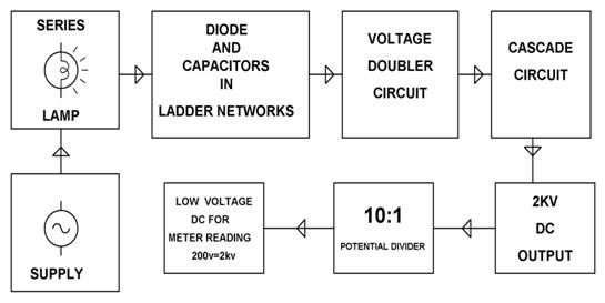
Block Diagram showing Voltage Multiplier Circuit
The system consists of an 8 stage
voltage multiplier unit. The capacitors are used to store the charge
whereas the diodes are used for rectification. As the AC signal is
applied, we get a voltage across each capacitor, which approximately
doubles with each stage. Thus by measuring the voltage across 1st stage of voltage doubler and the last stage, we get the required high voltage.
Since the output is a very high voltage, it is not possible to measure
it using simple multimeter. For this reason a voltage divider circuit is
used. The voltage divider consists of 10 resistors connected in series.
The output is taken across the last two resistors. The obtained output
is thus multiplied by 10 to get the actual output.
2. Marx Generator
With the development of solid-state
electronics, solid-state devices are becoming more and more suitable for
pulsed power application. They could provide the pulsed power systems
with compactness, reliability, high repetition rate, and long life time.
The rising of pulsed power generators using solid-state devices
eliminates limitations of conventional components, and promises pulsed
power technology to be widely used in commercial applications. However,
solid-state switching devices such as MOSFET or Insulated Gate Bipolar
Transistor (IGBT) available now are only rated up to a few kilo Volts.
Most of pulsed power systems demand much
higher voltage ratings. Marx modulator is a unique circuit intended for
voltage multiplication, as shown below. Traditionally, it employed
spark gaps as switches and resistors as isolators. Therefore, it had
drawbacks of low repetition rate, short life time, and inefficiency. In
this paper, Marx generator using solid-state devices is proposed to
combine the merits of both power semiconductor switches and Marx
circuits. It is designed for Plasma Source Ion Implantation (PSII) [1]
and for the following requirements:
The modern Marx generator using MOSFET
For reading the voltage and the time period please refer to the CRO screen sort.
- From the above low voltage demo unit we find input of 15 volt ,50% duty cycle at point A goes (–Ve ) also with respect to ground. Hence a high voltage transistor has to be used for high voltage. DURING THIS TIME ALL THE CAPACITORS C1,C2,C4,C5 GET CHARGED as seen at C upto 12 volt each.
- Then through proper switching cycle C1,C2,C4,C5 get series connected through the MOSFETs.
- Thus we get a (-Ve ) pulse voltage of 12+12+12+12=48 volts at point D
Application of Marx Generators – High Voltage DC by marx generator principle
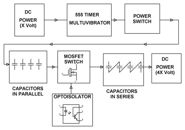
As we know by Marx Generator principle,
the capacitors are arranged in parallel to charge up and then connected
to series to develop a high voltage.
The system consists of a 555 timer
working in astable mode which provides a output pulse with 50% duty
cycle. The system consists of a total 4 stage multiplication stage, with
each stage consisting of a capacitor , 2 diodes and a MOSFET as a
switch. The diodes are used to charge the capacitor. A high pulse from
the 555 timer drives
the diodes and also the optoisolators which in turn provide triggering
pulses to each MOSFET. Thus the capacitors are connected in parallel as
they charge up to the supply voltage. A low logic pulse from the timer
results in the MOSFET switches being in off condition and the capacitors
are thus connected in series. The capacitors start discharging and the
voltage across each capacitor gets added, producing a voltage which is 4
times more than the input DC voltage.


No comments:
Post a Comment