


Why is Audio Level display needed?
Often in many applications, it is
required to measure the level of the audio signals, for example in
discotheques to get an idea about the loudness of the sound signal, in
other areas to measure the noise signal.
How audio levels of signals are displayed?
Often there are many ways to display the
audio level of the signal, one of them being the use of sound pressure
level meters, which simply calculate the change in pressure of the sound
signal. They are based on the fact that sound signals at different
frequencies have different pressure levels.
Another way is having a visualized
display of the loudness of the audio signal. Normally the display is in
form of a sequential glowing of LEDs to indicate the level of the audio
signal
By the term loudness, we mean the
magnitude of sound signal, perceived by each individual such that the
person can bear the sound pressure. For the same pressure, the loudness
of the sound varies for different frequencies.
The above two methods measure the
loudness of the sound or the volume in decibels. One decibel is
equivalent to 10 times the logarithm of the power of the sound signal.
Normally it is not feasible to have a large scale for the direct
measurement and hence the scale is shown mostly in decibels or dB.
Before going to details about the visualized audio level meter, let us have a brief idea about LM3915
LM3915
LM3915 is a dot/bar display driver which
drives a series of LEDs based on the analog input. It basically drives
each adjacent LED in 3DB steps i.e.in logarithmic way. It operates from
with a supply voltage of 3 V to 25 V.
LM3915 Pin Description
Pins 1, 10 to 18: Each
of these pins is connected to the cathode of the output LED. The anode
of the output LEDs are connected to the 3V to 20V supply.
Pin 2: This pin is the negative analog voltage supply and is usually connected to ground.
Pin 3: This pin is the positive voltage supply and usually the supply voltage is at min 3 V to max 20V
Pin 4: This pin is usually grounded
Pin 5: This pin is the signal input pin and the audio signal input is given to this pin.
Pin 6 and Pin 7 are shorted together. The current through pin 7 decides the current drawn by each LED.
Pin 8: It is the pin
used for adjusting the reference voltage. There is a resistance of
1.2kohms between pin 7 and pin 8 such that a voltage of 1.25V is between
the pins. A potential divider is connected to the resistor which is
used to adjust the reference voltage.
Pin 9: This is the mode
select pin and is used to select either the dot mode or the bar mode.
For the bar mode, the pin is connected directly to pin 3 , i.e. to the
positive voltage supply. For dot mode, the pin is left open, without any
connection.
How does LM3915 works?
LM3915 basically receives analog voltage
as input in the range between 0 to 1.5V and this is given to the Buffer
amplifier which drives a series of 10 comparators. There is a
reference voltage source which can be programmed. This reference voltage
is given to each comparator using a 1:10 Potential divider arrangement.
Each comparator compares the input voltage with a reference voltage and
accordingly drives the corresponding LED connected to it.
It can operate in dot mode or bar mode.
In bar mode, the LEDs are driven in continuous mode, i.e. the glowing of
LEDs appears as if in continuous form. In dot mode, a single LED glows
at a time.
Using a LM3914 / 15 IC U2 – Dot/Bar
Display Driver along with signal amplifier IC LM324 IC U1 to 4 a nice
dancing light as per audio signals are feasible. High power lamps can
also be used by adding opto coupler in series with the LEDs and the diac
of the opto driving the triac for 230 volt lamps. The entire display
system can operate from a single supply as low as 3V or as high as 25V.
Numerous mechanisms could be cascaded for a dot mode display or bar mode
display with an extent of 60dB or 90 dB. LM3915 can also be cascaded
with LM3914 for a linear/log display or with LM3916s for an
extended-range VU meter.
The LM3915 displays are used in audio
applications, power meter and RF signal strength meters. And these
displays are suited for signals with wide dynamic range, for example
audio level, power and etc.
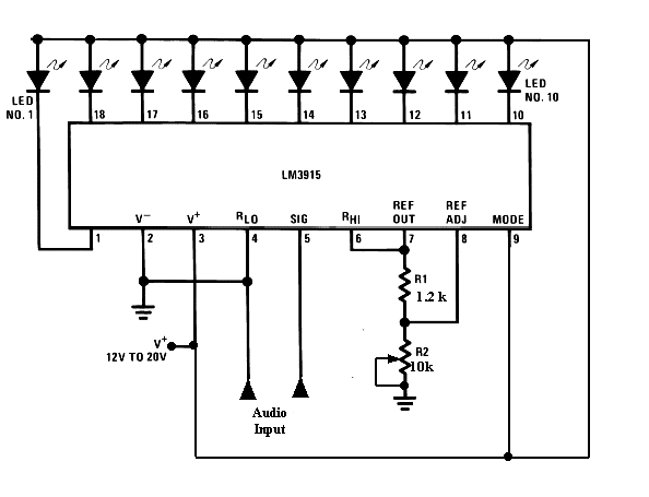
LM3915 as an Audio Level Meter
This circuit utilizes only one IC and
few external components. It displays the sound/audio level as far as 10
LEDs. The input voltage can vary from 12V to 20V, but we using only 12V
of voltage. The chip holds a flexible voltage reference and exact
ten-stage voltage divider. The high-impedance input buffer acknowledges
signals down to ground and up to within 1.5v of the positive power
supply. Further, it needs no protection against inputs of ±35V. The
input buffer drives 10 distinctive comparators referenced to the
accuracy divider. Accuracy is normally superior to 1dB.
Using the dot mode, the LED illuminated
represents the instantaneous value of the audio wave form. Both peak and
average levels can be easily observed. Since the dot will be constantly
moving, the LED’s are run at 30mA for sufficient power. The full-scale
reading is 10volts; that is easily adjusted by changing resistor R2. The
LM3915 signal input can with stand signals up to 35 volts. If there is a
chance that the audio input could exceed this range, either attenuates
it or include enough series resistance to limit the current to 5mA.
Application – Visualized Audio Level Meter
Let us have a detailed description about the visualized audio level meter

In the above given circuit, the audio
signal is first converted to electrical signal and this electrical
signal is further processed using a set of comparators to get the serial
input. Audio input signal voltage can be from a cell phone, TV audio or
a radio is maximum 6 volts.
The analog voltage input is given to the
IC LM3915. Initially the mode is set to be in bar mode. A switch is
used to set the mode in bar or dot mode. The IC accordingly performs
manipulations using the analog input and the LEDs are driven
accordingly. The LEDs start glowing after every 3dB change in the audio
level. Thus the audio level is displayed through the glowing LEDs at the
decibel level.
Now you have got an idea about the IC LM3915 if any queries on this topic or on the electrical and electronic projects leave your ideas section below.


No comments:
Post a Comment