


Now that you have a
fair understanding of what a semiconductor, and have studied logic
circuits - lets delve into some basic microchips. Microchips come in two
basic varieties - analog and digital. The key difference being how they
send signals through them. Either they deal with states of 1's and 0's
(digital), or they deal with varying levels of voltages and currents,
and are expected to pass them without any degredation. In either case -
there are some basic commonalities between them.
To begin with, they come in similar packaging... either DIP (Dual Inline Pins) with legs on only 2 sides, or postage stamp variety, with legs coming out from all 4 sides. They all require at least one bias voltage, and a ground. Some digital chips require a "clock" signal, while some analog may require a crystal oscillator input - with the key difference being whether it is an analog or a digital input. Finally, many analog chips can pass digital signals, and some digital chips can pass analog signals!
So what really determines whether it is a digital or analog chip? The answer lies in what the chip was originally designed to do. At the end of the day, a microchip is just a smaller version of a much larger "transistor" circuit. If the transistor circuit was an audio amplifier, then when it is miniaturized into a microchip - it is still an audio amplifier circuit, and would still reqire good fidelity - so it would be analog. If it is the microprocessor of a computer - it is a digital chip. Keep in mind that many types of equipment have both analog and digital chips in them. Why? Well, an MP3 player that stores music in digital format would be of little use if it couldn't play analog sound for your analog ears to hear - and that is but one example.
Lets look at some basic chips and see what they do. These are all chips that you WILL run into in the future:
The LM741 is a "simple" Operational Amplifier. A close look at the picture, and you see that there is a notch at the top. When you are looking at a microchip, (with the lettering facing you) there is always an identifying marker that tells where "pin 1" is. Usually it is a dot or a notch like this chip has, sometimes both. Microchip pins always go counterclockwise, so after finding the dot or the notch, pin one is the first pin counterclockwise from the notch.

The LM741 takes (roughly) 18 volts bias on pin 7 to operate, with ground on pin 4. Note that these voltages are relative. If your "ground" were floating at 30V, you could have the V+ at 30V plus 18V or 48 Volts, and the chip wouldn't know the difference - so long as there was an 18V drop between pins 4 and 7. Once we have the chip properly biased, we can start adding signals.
This particular chip has 2 pins it can take an input on (2 or 3). Recall that transistors invert (NOT) signals. So if you feed a transistor with another transistor - the signal is inverted twice. This anti-inversion (or non-inverted if you so please) makes the output the SAME phase as the input. Because it has 2 inputs, an inverted and a non-inverted - the circuit lends itself well to applications as oscillators - requiring positive feedback, and gain control - requiring negative feedback. Once we have bias, and feed the input to either of the two inputs - we should arrive at a larger, amplified output on pin 6. How amplified? That depends on how much amplification you want! By placing a resistor of the appropriate value, you can have either negative or positive gain, with a common mode gain of upwards to 90dB possible!
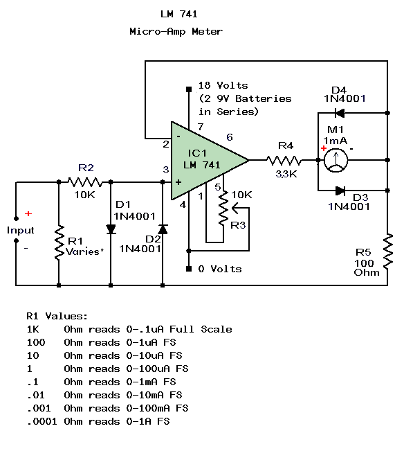
 To
the right you'll find a handy circuit - one that will find its place
onto any bona-fide electronics workbench. A Micro-Amp meter (a very
precision device)! Note the special "R1", which can be switched (you
pick the switching method - but I prefer an old fashioned 10 position
rotating switch). Depending on the value of R1, you have the ability to
accurately measure between 1/10th of a microamp all the way to 1 Amp! I
suppose you could modify it to go all the way up to 10 Amps, but I
wouldn't suggest trying 100 Amps - thats deadly current there, and most
likely your components wouldn't care for it. Also - notice that the
LM741 needs 18 volts to run it. That would be two 9 Volt batteries
connected in series connected across pins 4 and 7. If you want, you can
run a toggle switch between the
battery leads as an on-off switch to the circuit. Perhaps I'll add these
modifications in a later verion of the schematic. For now - feel free
to experiment and get back with me!
To
the right you'll find a handy circuit - one that will find its place
onto any bona-fide electronics workbench. A Micro-Amp meter (a very
precision device)! Note the special "R1", which can be switched (you
pick the switching method - but I prefer an old fashioned 10 position
rotating switch). Depending on the value of R1, you have the ability to
accurately measure between 1/10th of a microamp all the way to 1 Amp! I
suppose you could modify it to go all the way up to 10 Amps, but I
wouldn't suggest trying 100 Amps - thats deadly current there, and most
likely your components wouldn't care for it. Also - notice that the
LM741 needs 18 volts to run it. That would be two 9 Volt batteries
connected in series connected across pins 4 and 7. If you want, you can
run a toggle switch between the
battery leads as an on-off switch to the circuit. Perhaps I'll add these
modifications in a later verion of the schematic. For now - feel free
to experiment and get back with me!

Another very popular analog amplifier chip is the LM384, 5 Watt Audio Power Amplifier. The LM384 is a 14 pin package that is intended to use 28 Volts instead of the 18 used by the LM741. It is built heavy duty and can handle more power. More power means it generates more heat, and it will also burn up quicker - so it needs more of a "heat sink". Because of the heat problem it developes, 3 pins on each side of the chip are intended to be grounded to a large copper surface area on the board to dissipate the heat. As such pins 3,4,5, and 10,11, 12 respectively must be grounded heavily.
 To the right is another handy piece of test equipment for your home lab,
designed using the LM384. The Signal tracer is used to track down
problems in (typically) audio circuits, although it can also be used for
some video or RF amplifiers. In a pinch it can also be used for
"go/no-go" logic circuit testing (it will test if data is going through
the circuit - but not whether the data is correct). Connect a "test
probe" to the input of the circuit, then simply touch the probe end to
an audio circuit, and if there is sound - you'll hear it! Testing the
inputs and outputs of all the amplifiers, you can trace your way down
the circuit to where you can't find sound anymore, and you've localized
your problem.
To the right is another handy piece of test equipment for your home lab,
designed using the LM384. The Signal tracer is used to track down
problems in (typically) audio circuits, although it can also be used for
some video or RF amplifiers. In a pinch it can also be used for
"go/no-go" logic circuit testing (it will test if data is going through
the circuit - but not whether the data is correct). Connect a "test
probe" to the input of the circuit, then simply touch the probe end to
an audio circuit, and if there is sound - you'll hear it! Testing the
inputs and outputs of all the amplifiers, you can trace your way down
the circuit to where you can't find sound anymore, and you've localized
your problem.
 One
of the properties of semiconductor materials we've already discussed is
their ability to generate light when they conduct, which is the basis
of a Light Emitting Diode, or to conduct when they see light, which is
the basis of a photocell (photoelectric cell) or a solar panel. What
happens if we put an LED and a Photocell in a dark box, so that no light
can come into the box. When we apply power to the LED, it conduct, and
generates light, which will in turn cause the photocell to conduct,
turning it on (as a switch). This in fact is the method behind how an
Opto-coupler or Opto-Isolator works.
One
of the properties of semiconductor materials we've already discussed is
their ability to generate light when they conduct, which is the basis
of a Light Emitting Diode, or to conduct when they see light, which is
the basis of a photocell (photoelectric cell) or a solar panel. What
happens if we put an LED and a Photocell in a dark box, so that no light
can come into the box. When we apply power to the LED, it conduct, and
generates light, which will in turn cause the photocell to conduct,
turning it on (as a switch). This in fact is the method behind how an
Opto-coupler or Opto-Isolator works.
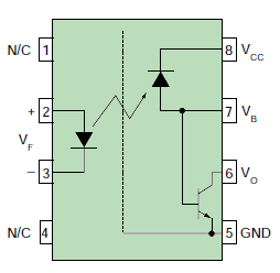
Pins 1 and 4 are not used. Bias for the device comes in on pin 8, with ground on 5. This leaves only pins 2,3,6,and 7 for inputs and outputs. Oddly, if you put an input signal on 7, you get output on 6 just like it were a normal transistor. Thats because it IS a normal transistor. However - if we leave pin 7 unused, and put an input signal across 2 and 3, it lights up the LED, which turns on the internal photocell, and applies power to pin 7. In short - we can use pin 7 as a troubleshooting tool. By monitoring the signal on 7, we can tell whether the LED is lighting up, and whether the photocell is working. Many pieces of equipment do this by putting an LED between 7 and ground as an indicator of whether input signal is applied or not. Now that we have signal on 2 and 3, we should see singal come out on 6 vs 5.
The CNW135 Optocoupler is one of the handiest devices around if you want to transfer either switching pulses, or low level signals betweeen two devices that may be riding at different ground levels.
Let me give you a practical example: Years ago, I needed to move a large satellite dish (think VLA). It used 3 very large motors, and took some high voltages and currents. In order to control its movements more precisely (I wanted it to be correct within 1/10ths of a degree), I needed computer accuracy. So I wrote a program that would read an input from a magnetic sensor, and calculate where the dish was at any time. From there, I simply had to find a way to get the computer to move the dish. The problem was that computer circuitry is sensitive, and I didn't want to connect my (at the time) expensive computer to a high voltage, high current motor. I decided to isolate the computer from the drive motors optically via an opticoupler.
CNW135 to the rescue. Because the two sides are "electrically" disconnected, but rather are connected optically, no electricity passes from the dish's drive motors to the computer. The outgoing signal from the computer lights up the Light Emitting Diode inside the CNW135 optocoupler, which turns on the Photocell inside the CNW135. This device "couples" the output of the computer (via the LED) to the input of the motor drive circuits (via the photocell). Now there was no more problem, and I could find any satellite in the sky without worry of destroying my computer.

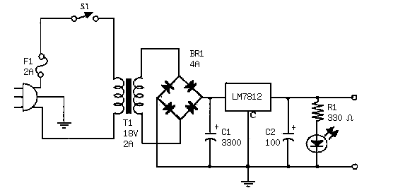
While the 7800/7900 series chips have only 3 pins, and more resemble a transistor than a microchip - do not be deceived. They have a very complex internal design for a very specific purpose. Modern electronic equipment is made to exacting specifications, and do not operate well with fluxuating voltage levels. In order to keep everything constant - the LM7800/LM7900 (as well as the MC7800/MC7900) series microchips are designed as high tech voltage regulators. In short - they do the same job as a zener diode, but are much more effective at it, and can handle more power.
The magic is in the "comparator" circuit. Lets say we are using an LM7812 (12 volt LM7800 series). If we have 15 volts coming in (too much), it passes the 15 volts to the Series Pass element. This "too high" voltage is seen at the Error Amplifier, which controls the internal "variable resistor" (actually a transistor), which sends current to ground, lowering the output voltage. In short - if the voltage coming in is higher than 12 volts, it drops it down until the output IS EXACTLY 12 volts. The Voltage Reference is basically an internal zener diode that is compared t the input by the Error Amplifier, which then Amplifies the difference (error) between what you want going out, and what you have coming in, and adjusts the Voltage Controller accordingly.
The first two letters designate the manufacturer. The last two numbers dictates what voltage it regulates to, so a MC7805 is a 5 volt regulator, and a LM7818 is an 18 volt regulator. The 7900 series is numbered the same way but regulates negative voltages. So an LM 7915 is a -15 Volt regulator.
 To the right is a handy tool for your workbench that uses an LM7812. No
work bench should be without a well regulated 12 Volt power supply.
Certainly you can build it, and have the pride and satisfaction of
saying you made it yourself, but I have to be honest with you. You can
purchase a 12 Volt power supply with decent regulation nowdays for far
less than the cost of building it yourself.
To the right is a handy tool for your workbench that uses an LM7812. No
work bench should be without a well regulated 12 Volt power supply.
Certainly you can build it, and have the pride and satisfaction of
saying you made it yourself, but I have to be honest with you. You can
purchase a 12 Volt power supply with decent regulation nowdays for far
less than the cost of building it yourself.
To begin with, they come in similar packaging... either DIP (Dual Inline Pins) with legs on only 2 sides, or postage stamp variety, with legs coming out from all 4 sides. They all require at least one bias voltage, and a ground. Some digital chips require a "clock" signal, while some analog may require a crystal oscillator input - with the key difference being whether it is an analog or a digital input. Finally, many analog chips can pass digital signals, and some digital chips can pass analog signals!
So what really determines whether it is a digital or analog chip? The answer lies in what the chip was originally designed to do. At the end of the day, a microchip is just a smaller version of a much larger "transistor" circuit. If the transistor circuit was an audio amplifier, then when it is miniaturized into a microchip - it is still an audio amplifier circuit, and would still reqire good fidelity - so it would be analog. If it is the microprocessor of a computer - it is a digital chip. Keep in mind that many types of equipment have both analog and digital chips in them. Why? Well, an MP3 player that stores music in digital format would be of little use if it couldn't play analog sound for your analog ears to hear - and that is but one example.
Lets look at some basic chips and see what they do. These are all chips that you WILL run into in the future:
- LM741 Amplifier
- LM384 Amplifier
- CNW135 Optocoupler
- 7800/7900 Voltage Regulator Series
- 7400 Logic Series
- 555/556 Timer
- 6502/6800/8000 Microprocessors
- PIC1650
- Common Analog Chips
- Common Digital Chips
Note that the above links point to the manufacturer's data sheets on each microchip.
LM741
The LM741 is a "simple" Operational Amplifier. A close look at the picture, and you see that there is a notch at the top. When you are looking at a microchip, (with the lettering facing you) there is always an identifying marker that tells where "pin 1" is. Usually it is a dot or a notch like this chip has, sometimes both. Microchip pins always go counterclockwise, so after finding the dot or the notch, pin one is the first pin counterclockwise from the notch.
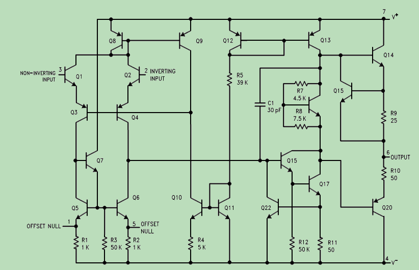
The LM741 takes (roughly) 18 volts bias on pin 7 to operate, with ground on pin 4. Note that these voltages are relative. If your "ground" were floating at 30V, you could have the V+ at 30V plus 18V or 48 Volts, and the chip wouldn't know the difference - so long as there was an 18V drop between pins 4 and 7. Once we have the chip properly biased, we can start adding signals.
This particular chip has 2 pins it can take an input on (2 or 3). Recall that transistors invert (NOT) signals. So if you feed a transistor with another transistor - the signal is inverted twice. This anti-inversion (or non-inverted if you so please) makes the output the SAME phase as the input. Because it has 2 inputs, an inverted and a non-inverted - the circuit lends itself well to applications as oscillators - requiring positive feedback, and gain control - requiring negative feedback. Once we have bias, and feed the input to either of the two inputs - we should arrive at a larger, amplified output on pin 6. How amplified? That depends on how much amplification you want! By placing a resistor of the appropriate value, you can have either negative or positive gain, with a common mode gain of upwards to 90dB possible!
 To
the right you'll find a handy circuit - one that will find its place
onto any bona-fide electronics workbench. A Micro-Amp meter (a very
precision device)! Note the special "R1", which can be switched (you
pick the switching method - but I prefer an old fashioned 10 position
rotating switch). Depending on the value of R1, you have the ability to
accurately measure between 1/10th of a microamp all the way to 1 Amp! I
suppose you could modify it to go all the way up to 10 Amps, but I
wouldn't suggest trying 100 Amps - thats deadly current there, and most
likely your components wouldn't care for it. Also - notice that the
LM741 needs 18 volts to run it. That would be two 9 Volt batteries
connected in series connected across pins 4 and 7. If you want, you can
run a toggle switch between the
battery leads as an on-off switch to the circuit. Perhaps I'll add these
modifications in a later verion of the schematic. For now - feel free
to experiment and get back with me!
To
the right you'll find a handy circuit - one that will find its place
onto any bona-fide electronics workbench. A Micro-Amp meter (a very
precision device)! Note the special "R1", which can be switched (you
pick the switching method - but I prefer an old fashioned 10 position
rotating switch). Depending on the value of R1, you have the ability to
accurately measure between 1/10th of a microamp all the way to 1 Amp! I
suppose you could modify it to go all the way up to 10 Amps, but I
wouldn't suggest trying 100 Amps - thats deadly current there, and most
likely your components wouldn't care for it. Also - notice that the
LM741 needs 18 volts to run it. That would be two 9 Volt batteries
connected in series connected across pins 4 and 7. If you want, you can
run a toggle switch between the
battery leads as an on-off switch to the circuit. Perhaps I'll add these
modifications in a later verion of the schematic. For now - feel free
to experiment and get back with me!
LM384 Amplifier
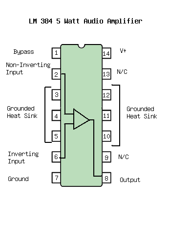
Another very popular analog amplifier chip is the LM384, 5 Watt Audio Power Amplifier. The LM384 is a 14 pin package that is intended to use 28 Volts instead of the 18 used by the LM741. It is built heavy duty and can handle more power. More power means it generates more heat, and it will also burn up quicker - so it needs more of a "heat sink". Because of the heat problem it developes, 3 pins on each side of the chip are intended to be grounded to a large copper surface area on the board to dissipate the heat. As such pins 3,4,5, and 10,11, 12 respectively must be grounded heavily.
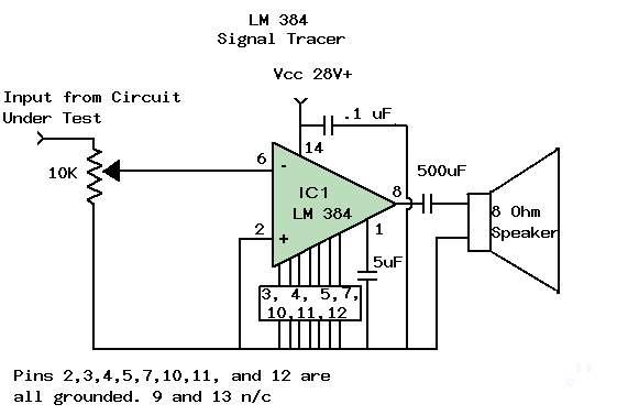 To the right is another handy piece of test equipment for your home lab,
designed using the LM384. The Signal tracer is used to track down
problems in (typically) audio circuits, although it can also be used for
some video or RF amplifiers. In a pinch it can also be used for
"go/no-go" logic circuit testing (it will test if data is going through
the circuit - but not whether the data is correct). Connect a "test
probe" to the input of the circuit, then simply touch the probe end to
an audio circuit, and if there is sound - you'll hear it! Testing the
inputs and outputs of all the amplifiers, you can trace your way down
the circuit to where you can't find sound anymore, and you've localized
your problem.
To the right is another handy piece of test equipment for your home lab,
designed using the LM384. The Signal tracer is used to track down
problems in (typically) audio circuits, although it can also be used for
some video or RF amplifiers. In a pinch it can also be used for
"go/no-go" logic circuit testing (it will test if data is going through
the circuit - but not whether the data is correct). Connect a "test
probe" to the input of the circuit, then simply touch the probe end to
an audio circuit, and if there is sound - you'll hear it! Testing the
inputs and outputs of all the amplifiers, you can trace your way down
the circuit to where you can't find sound anymore, and you've localized
your problem.
CNW135 Optocoupler
 One
of the properties of semiconductor materials we've already discussed is
their ability to generate light when they conduct, which is the basis
of a Light Emitting Diode, or to conduct when they see light, which is
the basis of a photocell (photoelectric cell) or a solar panel. What
happens if we put an LED and a Photocell in a dark box, so that no light
can come into the box. When we apply power to the LED, it conduct, and
generates light, which will in turn cause the photocell to conduct,
turning it on (as a switch). This in fact is the method behind how an
Opto-coupler or Opto-Isolator works.
One
of the properties of semiconductor materials we've already discussed is
their ability to generate light when they conduct, which is the basis
of a Light Emitting Diode, or to conduct when they see light, which is
the basis of a photocell (photoelectric cell) or a solar panel. What
happens if we put an LED and a Photocell in a dark box, so that no light
can come into the box. When we apply power to the LED, it conduct, and
generates light, which will in turn cause the photocell to conduct,
turning it on (as a switch). This in fact is the method behind how an
Opto-coupler or Opto-Isolator works.
Pins 1 and 4 are not used. Bias for the device comes in on pin 8, with ground on 5. This leaves only pins 2,3,6,and 7 for inputs and outputs. Oddly, if you put an input signal on 7, you get output on 6 just like it were a normal transistor. Thats because it IS a normal transistor. However - if we leave pin 7 unused, and put an input signal across 2 and 3, it lights up the LED, which turns on the internal photocell, and applies power to pin 7. In short - we can use pin 7 as a troubleshooting tool. By monitoring the signal on 7, we can tell whether the LED is lighting up, and whether the photocell is working. Many pieces of equipment do this by putting an LED between 7 and ground as an indicator of whether input signal is applied or not. Now that we have signal on 2 and 3, we should see singal come out on 6 vs 5.
The CNW135 Optocoupler is one of the handiest devices around if you want to transfer either switching pulses, or low level signals betweeen two devices that may be riding at different ground levels.
Let me give you a practical example: Years ago, I needed to move a large satellite dish (think VLA). It used 3 very large motors, and took some high voltages and currents. In order to control its movements more precisely (I wanted it to be correct within 1/10ths of a degree), I needed computer accuracy. So I wrote a program that would read an input from a magnetic sensor, and calculate where the dish was at any time. From there, I simply had to find a way to get the computer to move the dish. The problem was that computer circuitry is sensitive, and I didn't want to connect my (at the time) expensive computer to a high voltage, high current motor. I decided to isolate the computer from the drive motors optically via an opticoupler.
CNW135 to the rescue. Because the two sides are "electrically" disconnected, but rather are connected optically, no electricity passes from the dish's drive motors to the computer. The outgoing signal from the computer lights up the Light Emitting Diode inside the CNW135 optocoupler, which turns on the Photocell inside the CNW135. This device "couples" the output of the computer (via the LED) to the input of the motor drive circuits (via the photocell). Now there was no more problem, and I could find any satellite in the sky without worry of destroying my computer.
7800/7900 Series Voltage Regulators
While the 7800/7900 series chips have only 3 pins, and more resemble a transistor than a microchip - do not be deceived. They have a very complex internal design for a very specific purpose. Modern electronic equipment is made to exacting specifications, and do not operate well with fluxuating voltage levels. In order to keep everything constant - the LM7800/LM7900 (as well as the MC7800/MC7900) series microchips are designed as high tech voltage regulators. In short - they do the same job as a zener diode, but are much more effective at it, and can handle more power.
The magic is in the "comparator" circuit. Lets say we are using an LM7812 (12 volt LM7800 series). If we have 15 volts coming in (too much), it passes the 15 volts to the Series Pass element. This "too high" voltage is seen at the Error Amplifier, which controls the internal "variable resistor" (actually a transistor), which sends current to ground, lowering the output voltage. In short - if the voltage coming in is higher than 12 volts, it drops it down until the output IS EXACTLY 12 volts. The Voltage Reference is basically an internal zener diode that is compared t the input by the Error Amplifier, which then Amplifies the difference (error) between what you want going out, and what you have coming in, and adjusts the Voltage Controller accordingly.
The first two letters designate the manufacturer. The last two numbers dictates what voltage it regulates to, so a MC7805 is a 5 volt regulator, and a LM7818 is an 18 volt regulator. The 7900 series is numbered the same way but regulates negative voltages. So an LM 7915 is a -15 Volt regulator.
 To the right is a handy tool for your workbench that uses an LM7812. No
work bench should be without a well regulated 12 Volt power supply.
Certainly you can build it, and have the pride and satisfaction of
saying you made it yourself, but I have to be honest with you. You can
purchase a 12 Volt power supply with decent regulation nowdays for far
less than the cost of building it yourself.
To the right is a handy tool for your workbench that uses an LM7812. No
work bench should be without a well regulated 12 Volt power supply.
Certainly you can build it, and have the pride and satisfaction of
saying you made it yourself, but I have to be honest with you. You can
purchase a 12 Volt power supply with decent regulation nowdays for far
less than the cost of building it yourself. 


No comments:
Post a Comment