


The establishment of a connection
between the Silego GreenPAK and a smartphone app called Blynk creates a
basic smart home system.
As shown in Figure 1, the smart home structure works as a bi-directional network. It can be explained with two simple general examples:

Figure 1. Smart Home Architecture.
Controlling output components:
If the user wishes to turn ON a light bulb located inside the home, they simply have to press the button widget associated with the light bulb. After the request is generated, the Boolean data (LOW or HIGH) travels to the Blynk servers, which tell Arduino to turn the bulb ON. The Arduino then processes the data and begins the I2C transmission to the Silego GreenPAK (SLG46538V in this case, but it can work similarly with SLG46537V, SLG46533V and other common GreenPAKs with Asynchronous State Machine (ASM)). The value of the register 0xF4 is changed to 0x01, which turns the first bit of the register I2C block virtual output to HIGH. This is associated at the same time with pin 7 (light bulb) in GP design which forces that digital output pin to HIGH, energizing the relay through a circuit created. When the button in the button widget of the app is un-pressed, the output is turned OFF.Monitoring input sensors:
Let’s suppose at night when everybody is sleeping, an intruder decides to enter the house through a window. As soon as they try to open the window, an alarm and specific lights will be turned ON (it was set that way in GP Design). The Arduino will be frequently monitoring all the GP5’s connected sensors through I2C (reading the register 0xF0), so it will detect a change in the register value. As in our scenario, the value will be 0x08, which will mean that the digital input pin 4 is active, which will eventually turn a widget LED ON and send a notification to the app, prompting the user for security.Blynk Application
Download the app, and click on this link: http://docs.blynk.cc/. Anyone can create their own Blynk account. For the purpose of this app note, a project with some buttons, LEDs, tabs, email, notifications, slider, gauge, graph, and history graph has been created. (Figure 2).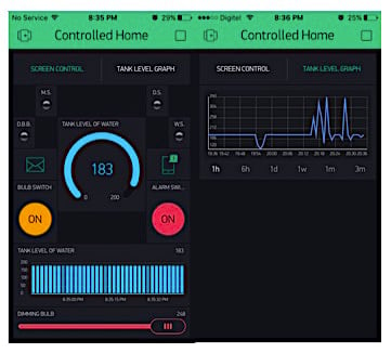
Figure 2. Blynk Smartphone HMI.
From there, it is simply a matter of configuring pins (hardware pins directly, or just virtual pins like in this project), and some other few options for each widget to get the Human Machine Interface (HMI) ready to run the target project.
Widgets justification:
- Buttons: There are a couple of buttons: one to activate light bulb, and the other one to activate the alarm buzzer, both are independent.
- LEDs: There are four LED widgets, indicating the status of each sensor, such as: movement sensor (as M.S.), doorbell button (D.B.B.), door sensor (D.S.) and window sensor (W.S.)
- Tabs: Enable optional tabs to organize the widgets better.
- Email: Enable email notifications
- Notifications: Enable smartphone notifications
- Slider: one slider to set the counter data value (0 to 248 on this case) of the CNT6/DLY6 in GP Design
- Gauge: One gauge to show the level of water of the home’s tank
- Graph: One graph to show the level of water of the home’s tank (same as gauge widget).
- History Graph: to show data statistics of the water tank level through the time (from hours to months of data storage)
Notifications events:
Two kinds of notifications are supported: by email and via smartphones (you can also add twitter notifications). You'll need to add the notifications widgets into the app, and write the correct functions from the Blynk library on Arduino IDE, to enable notifications module. See Figure 3.
Figure 3. Notifications examples.
ESP8266 Wi-Fi Module
The ESP8266 is a Wi-Fi chip with a full TCP/IP stack and Micro Controller Unit capability. Through some libraries and protocols, you can not only achieve communication with your hardware, but also a stabilize one too.achieve goodnicate with any other microcontroller or programmable device through UART protocol, via pre-programmed AT commands inside the chip.There are many kinds of ESP8266 modules, but for this project the ESP8266-01 is being used. It’s connected to the Arduino as shown in Figure 4:

Figure 4. Arduino Mega and ESP8266 Wiring Diagram.
The Wi-Fi module works with 3.3V levels, so there are two options: the simpler one is shown in Figure 4. It involves connecting ESP8266’s VDD pin to the 3.3V pin of Arduino, and Arduino’s TX to a voltage divider (converting the 5v to 3.3V), and then wiring that output voltage level to RX pin of the module. The other option is to buy a voltage level converter chip (or maybe a 3.3V power source board) to feed the ESP8266 circuit.
Blynk libraries will get requests to control the entire module via AT commands: from connecting to your WLAN at home, to sending and receiving as many data bytes as you need.
The I2C protocol in SLG46538V is a tool for many kinds of projects. For this one, the GreenPAK ASM is used as a I/O pin extension, leaving almost all the pins free on the Arduino. There are some app notes available (such as AN-1107 and AN-1090), where I2C is well explained. Almost all the GreenPAK device hardware can be controlled from I2C: configuring a general microcontroller as a Master, and GreenPAK as a Slave. Via I2C, sending some byte commands, pins, ASM RAM, counters, LUT and many other elements in the GreenPAK can be read and written.
The GreenPAK design is based on the GPIO pins, and the I2C protocol tool blocks connections. Digital inputs such as a movement sensor, door sensor, window sensor and door bell push button in the automated home are associated with pins 2, 3, 4 and 5 respectively. They can easily be read from I2C tool, but also it’s well designed with gates (LUTs) to trigger one or both of the digital outputs included on the project. For example, when a door bell push button is pressed, it will activate the alarm to simulate just the doorbell sound. When the Movement Sensor detects someone it will turn the lights ON (simulating someone in a room). Finally, if door sensor or window sensor (through Hall effect) detects some intruder, they will trigger the alarm and lights at the same time.
There is also a dimming light bulb at pin 10, connected to two counters which have this pin as a PWM output, where CNT0/DLY0 sets the frequency (100Hz) and CNT6/DLY6 sets the pulse width from 0 to 255. However, there is an error range of approximately 3% to set the output width, so it’s suggested to send bytes from 0 to 248 from Blynk app, to get a great PWM.
Furthermore, part of the ultrasonic sensor circuit is controlled by the GreenPAK ASM. It controls the trigger pulse of the module through two counters: CNT3/DLY3 to set the frequency (10Hz) and CNT4/DLY4 to set the pulse width necessary to activate the sensor circuit process, thereby creating an “echo” output which will be received by the Arduino board to process the data.
The I2C block is connected as default with pin 8 (SCL) and pin 9 (SDA). The device address is 0x00, but any other address from 0x00 to 0xF can also be set. It is important to know (Based on SLG46538V datasheet) that I2C writing frame is composed of a start bit, followed by a control byte, word address, data and a stop bit (Figure 7 illustration). I2C reading frame is composed of a start bit, followed by a control byte, word address, a start bit (again), control byte, data and stop bit to end the transmission (check the app note AN-1090 for more information about how I2C works).
Arduino Code
For Arduino (from the hardware perspective), there is not much to update, apart from the connection to the Wi-Fi module. Echo pin output of the ultrasonic sensor is connected to Arduino’s digital input pin 12. This way the Arduino can process echo pulse data (Talked more about below).Regarding Arduino code design, some libraries were used that solve many things and makes programming easier. These libraries are: “ESP8266_Lib.h”, “BlynkSimpleShieldEsp8266.h”, “SimpleTimer.h” and “Silego.h”. The code is well commented and explained (check it out by downloading the Arduino file). Some general things are explained:
                    // You should get Auth Token in the Blynk App.
// Go to the Project Settings (nut icon).
char auth[] = "YourAuthToken"; // replace "YourAuthToken" for the token number of the Blynk project
// Your WiFi credentials.
// Set password to "" for open networks.
char ssid[] = "YourNetworkName"; // replace "YourNetwokName" for the name of your network
char pass[] = "YourPassword"; // replace "YourPassword" for the wifi password
To install the project at home, the Auth Token number has to be typed. To find it, just open the Blynk app, log in with your account (if you have not created one, just register), create a project, and go to project settings. There, the Auth Token number (check the example in Figure 10) can be seen. Once you find it, just type the number in the Arduino code, or to make things easier, send that code to your email over the app. Then it can be just copied and pasted in the PC. In addition, the name and the password of the WLAN have to be typed, as any other Wi-Fi based electronic device.

Figure 6. Project Settings.
If working with LED widgets in the app is desired, just add as many WidgetLED objects as desired in Arduino code. For this app note, all sensors that are used to build the project have been added.
There are other important objects to define such as Wi-Fi from ESP8266 library classes and timer from simpler timer classes.
Also, the Address of the GreenPAK ASM has to be defined, in this case, 0x00.
                    ESP8266 wifi(&EspSerial);

WidgetLED movementSensor(V2); // Creating Widgets using virtual pins on Blynk
WidgetLED doorSensor(V3);     // There are a large virtual pins available to use
WidgetLED windowSensor(V8);
WidgetLED doorBellButton(V4);

SimpleTimer timer;
Silego silego(0x00); // GreenPAK ASM I2C slave Address
If any value has to be written from the app to a virtual pin, the recommended way to work with it is a function called BLYNK_WRITE(Virtual pin name), to know the virtual pin that’s to be read from Blynk. That has to be followed by typing the pin’s name as a parameter in the function. In this way, param.asInt() has to be called within the function, which returns an integer value (It could be a byte or Boolean too), that has to be processed to create a trigger to execute other sentences in the code.
                    BLYNK_WRITE(V0) //Button Widget is writing to pin V0
{
  int statusBulb = param.asInt(); // Saves Light Bulb status

  if (statusBulb) {
    silego.writeI2C(0xf4, 0x01); // Set GP5's pin 7 HIGH (Light Bulb) by the virtual pin 0 in GP Design
  }
  else {
    silego.writeI2C(0xf4, 0x00); // Clear register 0xf4 (all virtual inputs)
  }
}
It is very important while using Blynk with Arduino, to leave the void loop function, with only Blynk.run() function if possible, and avoid any kind of long millisecond delays with delay(). The consequence of this could halt the communication between Arduino and Blynk, or delay data transmission. However, it is always desirable to add some other features to the Arduino code in addition to what the app services offers, and that’s why timer.setInterval(milliseconds, functionToExecute) from “SimplerTimer.h” function is used in the code’s setup, to check a general purpose project function that’s needed to execute it to add other features. For this example it is timer.setInterval(100L, readInputs), that means for each 100 milliseconds, Arduino will run the function readInputs().
                    void setup()
{
  pinMode(echo, INPUT); // echo from ultrasonic sensor connected on pin 12
  // Set console baud rate
  Serial.begin(74880); // Any baud rate desired
  delay(10);
  // Set ESP8266 baud rate
  EspSerial.begin(ESP8266_BAUD); //74880 of baud rate
  delay(10);

  Blynk.begin(auth, wifi, ssid, pass); // This function connects ESP8266 to wifi network
  // and then with Blynk servers

  timer.setInterval(100L, readInputs);
}
readInput() function, is one of the most important functions in the project because it reads the GreenPAK digital inputs with the I2C tool, then it evaluates the returned byte number to know what sensor is being activated. Once Arduino knows what sensor it is reading, it triggers (turns ON) the associated LED widget by writing to the virtual number object previously set up. This way, the user can observe when a sensor detects something by just checking the app, but this will also trigger some notifications with Blynk.notification() function; e.g. Arduino reads GreenPAK ASM and knows that movement sensor detected someone, so it will trigger movementSensor.on(), and a notification to the smartphone saying “There is someone in the Living Room”.
                    void readInputs() {
  readingByte = silego.readI2C(0xf0); //read input pins associated to 0xf0 register

  switch (readingByte) {
    case 0x02: // if input pin 2 is HIGH
      movementSensor.on(); // Blynk's movement sensor widget LED is ON
      doorSensor.off();
      windowSensor.off();
      doorBellButton.off();
      Blynk.notify("There is someone in the Living Room"); // Sends the notification to your smartphone
      break;

    case 0x04: // if input pin 3 is HIGH
      movementSensor.off();
      doorSensor.on();      // Blynk's door sensor widget LED is ON
      windowSensor.off();
      doorBellButton.off();
      Blynk.notify("ALERT. An intruder opened the Door"); // Sends the notification to your smartphone
      delay(10);
      Blynk.email("your_email@mail.com", "ALERT", "An intruder opened the Door"); // Sends the notification to your email
      break;
Finally, this function also reads ultrasonic echo pin, through a function called pulseIn(), it measures how long the echo pulse remains HIGH in microseconds, then it translates that time into centimeters, using the following formula: distance=microseconds/58 (check the app note AN-1050 for more information about how ultrasonic sensor works); Once the value of distance is known, Blynk.virtualWrite() function is used to write any virtual on Blynk e.g. for this Smart Home design module, the distance value is sent to virtual pin 6 and 7, where virtual pin 6 is associated to a gauge widget, and pin 7 to a graph widget in the app, to show how this variable behaves (simulating the water level of the tank through distance).
                    // This part covers the ultrasonic's echo pulses processing
  duration = pulseIn(echo, HIGH); // Counts the time echo pin is HIGH in microseconds and saves it
  distance = duration / 58; // translating that time duration to centimeters, so we can know
  // e.g. the distance between water and the sensor in a water tank
  // So this will calculate how much water is in the tank at home, if you
  // place it at the top of the tank, facing down to the water

  Blynk.virtualWrite(V6, distance); // It sends the distance value to two different Virtual pins for X purpose
  Blynk.virtualWrite(V7, distance); // inside Blynk app

  if (distance > 100 & distance < 150) {
    Blynk.notify("Tank level is below 50%"); // Sends the notification to your smartphone
  }
  else if (distance > 160 & distance < 200) {
    Blynk.notify("Tank level is below 20%"); // Sends the notification to your smartphone
  }
}
Regarding tank’s level notification, some basic conditions were used: to tell the user when the water level is low and when it is between 100-150cm (this means that the water level is below 50%). Also, when it is between 160-200cm, the water level is below 20%.
Note: For an easier simulation of the water tank level, the moment when water level notifications occur in the video demonstration was changed; therefore when the water was between 100-50cm, the water level was below 50%; when it was between 40-0cm, the water level was below 20%. As can be observed, conditions were inverted just for simulation demonstration in the project’s video.
GPIO Relevant Circuit Schematics
A common isolated circuit (with optocouplers and a 5V relay and 120VAC output on the normally open pin) was applied to the light bulb’s digital output. (See Figure 8)For the rest of the circuits, sensors as digital inputs are connected directly to the GreenPAK ASM. The other digital outputs (like the buzzer and the LED) are connected directly with some basic resistors to protect them.
Conclusion
The GreenPAK ASM chip is an effective device to utilize IN Smart Home systems’ designs. Just imagine setting sixteen (16) GreenPAK as slave devices controlled by a master microcontroller, how many sensors and elements can be controlled with that system? Even a whole building can be controlled in many aspects with a very low-cost solution, (at least from the controller part in the system’s architecture).B.O.M and Tools
The components and tools used in the project are:
- SLG46538V GreenPAK Device
- Arduino Mega 2560
- ESP8266-01
- HC-SR501
- HC-SR04
- US1881 (2)
- Alarm buzzer
- GreenPAK Designer
- Arduino IDE
- Blynk
Other components and tools:
- LEDs
- Resistances
- 5V relay
- PNP and NPN common transistors
- Push button
- Dupont cables
Industry Articles are a
form of unpaid content that allows industry partners to share useful
news, messages, and technology with All About Circuits readers in a way
editorial content is not well suited to. All Industry Articles are
subject to strict editorial guidelines with the intention of offering
readers useful news, technical expertise, or stories. The viewpoints and
opinions expressed in Industry Articles are those of the partner and
not necessarily those of All About Circuits or its writers.


No comments:
Post a Comment