Maxim Integrated recently announced their new Himalaya uSLIC power modules: the MAXM17532 and the MAXM15462.

While both ICs are 10-lead devices, their pinouts are not identical. Images taken from the two MAXM15462 (PDF) and MAXM17532 (PDF) datasheets.
The MAXM15462 vs. MAXM17532: Similarities and Differences
If you're considering using one or both of these voltage-regulator solutions in upcoming designs, then be sure to review, and understand, their datasheets because they definitely have some differences.Similarities
A handful of similarities between the MAXM15462 and the MAXM17532 include:- wide-input voltage ranges of 4/4.5V to 42V;
- high efficiencies, on the order of 90% (check out the various efficiency plots in the datasheets' sections entitled Typical Operating Characteristics);
- compliance with “CISPR22 (EN55022) Class B conducted and radiated emissions”;
- passing of “drop, shock, and vibration standards: JESD22-B103, B104, B111”;
- output currents are rather limited (i.e., low); 100mA (MAXM17532) and 300mA (MAXM15462);
- both are fully integrated—meaning that in addition to the buck regulator, these ICs come with built-in FETs, compensation circuits, and an inductor, which makes them ideal for space-constrained applications.
Differences
The following table includes some differences—granted, some are fairly minor—that I feel are worth noting:A quick comparison between the two power modules. Table created by Nick Davis.
Plots, Guidance, and Tips
Plots
Within each of the two datasheets, Maxim has been generous enough to provide various plots related to these power modules, including efficiency waveforms (mentioned previously), line and load regulation plots, switching waveforms, start-up characteristics, and more. So, if you're interested in diving into the details related to these topics, check out each datasheet's section entitled Typical Operating Characteristics. You will find between four and six pages of plots, depending on which datasheet you're viewing.Guidance and Tips
In an effort to help designers more easily and successfully implement these ICs, Maxim has provided example PCB layout designs (see the image below) as well as briefly discussing a few important points, which should be taken seriously during the layout phase.
Maxim provides helpful layout design assistance through words and images. Taken from the MAXM17532 datasheet (PDF).
Also, Maxim provides recommended component values (see the following figure) for common VIN and VOUT selections. To learn more about these tips and suggestions, check out the datasheet sections entitled Application Information.

This table makes it super easy for choosing components based on common VOUT voltages. Table courtesy of the MAXM17532 datasheet (PDF).
Available Evaluation Kits
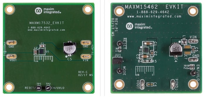
If you're interested in testing one, or both, of these seemingly super-small voltage-regulator solutions, then consider purchasing their evaluation boards. The MAXM17532 evaluation board—the MAXM17532EVKIT—is designed for 5V output-voltage applications. And if you're looking for a 3.3V output-voltage version of the MAXM15462, consider the MAXM15462EVKIT.
As can be observed from these evaluation board pictures, the Himalaya uSLIC Power Modules are indeed small in size. Images courtesy of Maxim Integrated.
Have you had the opportunity to use either or both of these ICs from Maxim Integrated in any of your designs? Or, have you been able to test the ICs by use of the evaluation boards? If so, leave a comment and tell us about your experiences.


No comments:
Post a Comment