


In this project, we'll build a device that can detect Wi-Fi signals and "react" accordingly. Next up: firmware.
In this article, we'll focus on the hefty amount of firmware in this project.
Compiling the Firmware
Let’s sort out the software first, which I find is the most annoying part. The good news is that you only need to do it once—afterward, you'll have all the open-source tools and code that I used to write the firmware.Arduino IDE ~1.6.12 (Application)
This is available for Linux, Mac, and Windows. You may already have this software if you’ve done development with microcontrollers before. If not, I encourage you to read/watch a few tutorials to get up to speed.
FTDI Drivers (OS Device)
Operating System Drivers for your FTDI adapter. If you plug the adapter in and a serial/COM port appears, you’re good.Many adapters use the same Cypress USB chip that’s on the Arduino, so you may have drivers already. Otherwise, your adapter should have come with a disc or instructions to download them from the internet.
esp8266 ~2.3.0 (Board Target)
Inside the Arduino IDE, use the “Tools/Board/Boards Manager…” menu option, and search for “esp8266”. Install this if it's not already there. This allows the IDE to compile code for the new (non-Atmel) microcontroller. (And, hopefully, other variants like the ESP32 in the future.)
Libraries are added to the Arduino IDE via the “Sketch/Include Library/Library Manager…” menu option.
FastLED ~3.1.3 (Library)
Open the library manager and search for “FastLED”. This controls the Neopixel and is another very common library you might already have.
ArduinoJSON ~5.7.2 (Library)
Rather than inventing my own file formats for configuration files and data packets, I figured I might as well just use a tried-and-true format that everyone already knows.
ESP AsyncTCP & Async WebServer ~1.0.0
This is the http/websockets server that is the foundation of the Eye's admin interface and the library you're least likely to already have.
Wi-Fi Eye (Sketch)
And finally, this is the "sketch" code that I wrote. Either download and uncompress the .zip file, or use the GitHub desktop tools to clone the repository (for extra points, start a new branch for your build).Then just open the “WifiEye.ino” file and the Arduino IDE should load up and you will be looking at a screen full of C++ code.
Pre-Check Compile
Plug your FTDI adapter in and a new serial port should appear in the IDE under “Tools/Port”. Select it and make sure the following IDE options are set:
Press the “compile and upload” arrow and the IDE will chug away for quite a while compiling libraries and generally getting ready for the ESP8266.
Eventually, the upload should start and fail because there’s no target board plugged in yet. If it doesn’t get that far (because of compiler errors or other shenanigans), you’ll need to sort that out before proceeding. Check the discussion boards—it’s probably an API change again.

Successful compile, but no microcontroller plugged in yet.
You should also have an option under “Tools” called “ESP8266 Sketch Data Upload”. This utility does not upload the main sketch (the arrow button does that already). It uploads the contents of the sketch /datadirectory to the SPIFFS Filesystem on the microcontroller’s “flash drive” (in our case, all the config and content files the webserver needs). There have been some changes around this utility recently and it may not install with the rest of the library anymore. But you’ll need it.
If all that works then our programming station is ready to write firmware down the wire to our controller and we can get to the easy part involving wire strippers and solder.
Wiring up the ESP-12F for Programming
The ESP8266 is the chip, but you’ll find it on modules named “ESP-1” all the way to “ESP-13”. What differs is the amount of flash memory onboard and how many of the GPIO pins are routed to accessible connectors.I’ve been designing around the “ESP-12E” or “ESP-12F”, which has 4MB of flash, an onboard antenna, and the majority of the GPIO pins available around the edge. The signature of these modules is the tin RF shield with the “AI” stamp on the front. The main difference between the “E” and “F” is that third row of pins at the bottom which, actually, you’re never going to use. Also, the shape of the antenna differs slightly.
They’re well-constructed, robust, and—while the pins are an annoying 2.00mm apart (so standard 2.45mm IDC pin rows don’t fit)—they’re still easy enough to solder to directly.

Minimal parts needed for programming. (FTDI adapter not shown.)
To get the ESP12-F module to boot properly, we need to add two wire links: route Enable to Vcc and GPIO15 to GND.
Now the module will boot up from the internal flash when power is supplied. Yes, it would be correct to use a pull-down resistor for GPIO15, but just leave it alone in software and you'll be fine. We're being cheap.
To put the bootloader into firmware update mode, we need to pull GPIO0 to GND during reset. This is most easily done with a small external switch or a jumper. A really, really cool hacker would just short those pins with one hand while plugging into USB with another, but I don't recommend it. It would be irresponsible of me to even suggest using a paperclip.
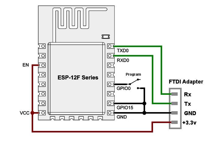
Minimal setup for boot/programming mode (as seen from the top of the module).

Now, here’s the thing: once we’ve used this wire interface to upload our firmware, it’s likely we’ll never use it again because the ESP8266 has over-the-air (OTA) programming. OTA programming is more convenient (you get a list of devices to choose in the IDE) and much faster, too (there’s more bandwidth on Wi-Fi interface than over serial).
We’ll only need it again if we screw up the firmware so badly that it can’t physically boot anymore, or it goes into a reset loop—which, if you’re sensible, is rare. I spent two months developing the firmware on the original Eye prototype purely doing OTA uploads and never broke it (it didn’t even have a wired programming port. That’s called “incentive to get it right.”).
Even if the OTA update fails mid-connection (it’s Wi-Fi, after all), the device is not left in a half-programmed, unbootable state. You just have to keep retrying until it works.
I’ve personally standardized on 4-pin mini JST connectors. They’re tiny, rated up to an amp, come in year-supply packs for a couple of dollars, and the color coding is nice. 5-pin connectors would probably be even better, allowing the program switch to be externalized too.
After using this connector for the initial firmware upload, it will be repurposed as the main power plug to the voltage regulator. If your project has some kind of serial port capability, those pins are still accessible. If we need to reflash the hard way again, we’ll swap plugs to the programmer and put the switch back.

Now is a good time to double-check your FTDI adapter is definitely set to 3.3V and all the connections are the right way around. Then plug the microcontroller into the FTDI adapter, make sure nothing’s shorting on anything metal, cross your fingers, check the location of fire extinguishers, and then plug the FTDI adapter into your computer via the USB cable.
There should be no smoke, and the briefest of blinks from the LED on the ESP-12 module.
If there is smoke, you should stop and deal with that.
The module may get warm, but it should not get so hot you’re fearful of touching it. (Note that it will get scorchingly hot at 5v if you didn't set your adapter correctly.)
If you like, you can fire up a serial terminal (at 115200 baud) and—depending on whether you’ve got the programming switch on or off and what firmware is already on it—you will see anything ranging from binary-looking garbage (usually the bootloader saying “whazzup?”) to an AT “modem” command line (which usually responds to blank lines with “ERROR”) or even a LUA or Python interpreter. The blue LED should flash in time with serial communications.
The programming mode switch only needs to be on during the initial moments of boot, so make sure that’s set, reboot (power cycle) the ESP, and click the “Compile and Upload” arrow in the Arduino IDE again.

Successful upload.
This time, the upload should proceed properly. You’ll get progress dots in the IDE and the blue LED will flash like mad for a while. Eventually, the ESP will reboot.
However, we haven’t uploaded our config files yet. Use “Tools/ESP8266 Sketch Data Upload” to transfer the contents of the flash filesystem. You may need to reset / power cycle the ESP again, to get back into programming mode. This upload will take a lot longer (many minutes) then it will reboot again. After that, turn the “programming mode” switch off.
Once the blue LED comes on and stays on, that means our new firmware is uploaded and running. (Why does it stay on? Something to do with FastLED. Long story.)
Setting up the Network Connection
If the above process works, you should be able to use a mobile device to find a Wi-Fi access point called Agomotto and connect to it using the password shamballa, and then use a browser to go to the URL http://192.168.4.1 and the web interface should appear.

Did you notice that we didn’t modify a single source file before upload? Usually, there’s a step where you have to hard-code your local access point name and password into the IoT firmware. We didn’t do that (although you can).
Instead, use the web interface to browse through the available options. You can dynamically connect to any visible access point (after typing in the correct password, of course) just as you would on a normal laptop or mobile.

You may need to save the settings and reboot to get some options to stick—the code still isn't perfect at 'live' config updates.
However nice the interface is, it’s also very convenient to have the device auto-connect to your local network on first boot (especially if you don’t have a mobile handy to configure it), and so before doing the “Sketch Data Upload” you can create an entry in the sketch /data/wifi/ap directory with your own network configuration.
eg: If your WiFi Access Point is called “Moria”, add a file named “/ap/wifi/Moria” (same capitalization) with the contents:
                    {
    "password":"YouShallNotPass",
    "priority":10,
    "auto":true,
    "ota":true
}
This instructs the firmware to auto-connect to an access point called “Moria” with the given password and turn on Over-The-Air updates once it does. If more than one option is available, the access point with the largest priority is tried first.
Make sure this file is strictly valid JSON. Names must be in quotes, no extra commas at the end. If the file isn’t having any effect, it’s likely because of a syntax error.
This is very different from compiling it into the firmware because these settings can be changed afterward via the web interface, or even uploading new files with authenticated http requests.
The nice thing about OTA is that it uses the “Bonjour” protocol to broadcast presence, so after a while, the new IoT device will list itself under the “Ports” menu in the Arduino IDE (sometimes often a long while, ten minutes or more). That’s nice because otherwise, it’s really hard to figure out what IP address your fresh device was allocated by the local network.

Agomotto appears as a Network Port under the IDE "Tools" menu, and can now be programmed "Over The Air".
If the discovery process is taking too long on Windows (MacOS is probably much better) there’s a program called Bonjour Browser which seems to give Windows a kick in the pants for looking around. I might be imagining it. Restarting the IDE sometimes helps too. It's not a perfect process yet.

If Agomotto isn’t appearing on the network, and you don’t have a Wi-Fi client to check the interface, you might need to monitor the serial port and see if there are any messages coming out (either error messages or the IP address should be reported once assigned). Or, you can use various network scan tools (or broadcast pings) to try to find it.
Once you know what IP address was allocated to the Eye by your network, use your desktop browser to go to that address url. Eg: 10.1.1.18 on my network. Most modern browsers should be compatible, so long as they implement the newer HTML5 APIs. I prefer Chrome, but Mozilla, iOS and IE10 should be mostly fine.
Note there is very little security for this admin UI (in fact, it's how you modify the security). The assumption is that whether you connect to the Eye from a mobile device (thus proving you know the WiFi password) or you command the Eye to make itself available on a network, everyone on that network with a browser is considered "trusted". That's not good enough for hostile environments, but it's a security step up from "none at all".
If all that works, then congratulations! Your tiny robot brain is ready!
Now you can monitor, control, and reprogram your droid wirelessly from anywhere in the house. We could remove the switch now, but you know we'll only need it again if we do. Leave it for a bit.

This is the point where you can commit to buying those super-expensive $5 servos, LiPo batteries, and a nice roll of 3D printer Filament (or styrofoam and paints if you prefer) and start thinking about the physical mechanics for next time.
With that, the circuit diagram, and the controller we’ve already built, you could probably work out the rest.
Just please remember the context here as I continue to update the code: You should assume the microcontroller will crash regularly and the servos will go totally crazy at random. If you’re using it to control anything life-threatening or razor-sharp, then you’re crazy, too. (The fact my Eye stays running for days at a time longer than my Windows machine is not relevant or even a very high bar.)
Next Time…
Next, we do some body-building! We’ll have a good talk about servos and 3D printed “cases”, assemble some twitchy robots, and look deeper into what the interface can do.


No comments:
Post a Comment