


In this teardown, we take apart Ancel's vehicle code reader OBD-II
scanner, the AD410, to see if we can find anything interesting.
If only I had had this tool about three months ago when my truck's service engine light appeared, I could've saved myself a trip to the local auto parts store where the code was read, interpreted, and cleared. This code-reading and code-clearing device looks like a pretty handy tool for any DIY automotive repair enthusiast.
Well, let's take a look under its hood (pun intended)!
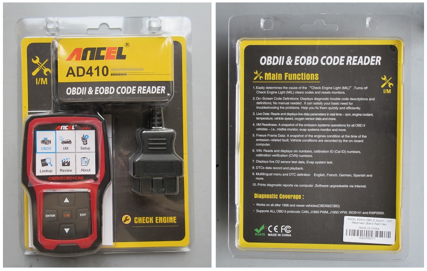
The packaging of Ancel's AD410 vehicle code reader, which is both functional and inexpensive
What's Included in the Box
Besides the vehicle code-reading device, itself—along with its integrated cable and OBD-II connector assembly—the code reader comes with a user's manual and a micro-USB-to-USB cable, which allows the user to print diagnostic reports via a computer. Nice! See the image below.
What's included with the AD410 code reader
Disassembly Was a Snap
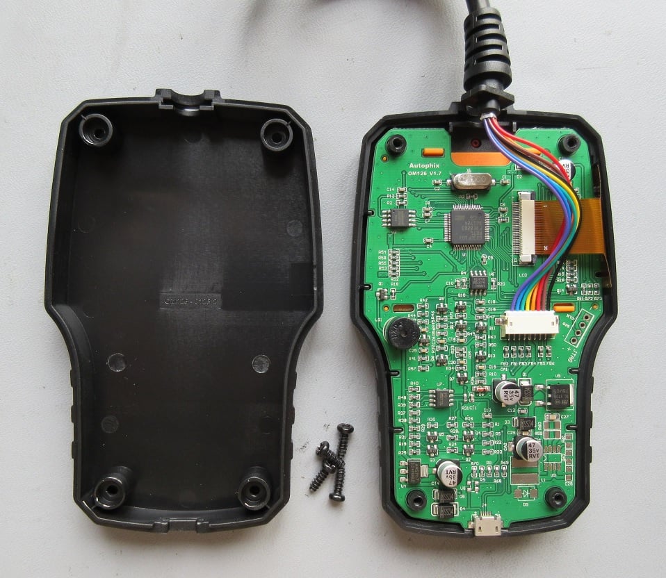
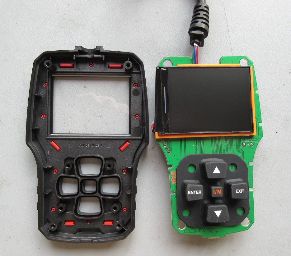
I was a bit surprised at how easy the code reader's enclosure came apart. Only four Phillips-head screws hold the two plastic enclosure pieces together. However, both plastic pieces feel robust, which is necessary for protecting the device should it accidentally be dropped on a garage floor.Once the two enclosure halves were separated, the single internal PCB readily lifted out. See the two images below.
The two enclosure pieces are easily separated once the four Phillip screws are removed.
The PCB easily is removed from the enclosure by simply lifting it out.
The LCD Screen
Integrated with the LCD screen, which is supported/protected by an orange plastic cover, is a flex circuit that connects to the PCB via an SMD connector.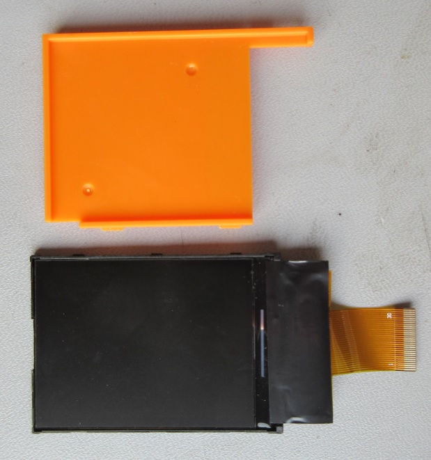
The LCD display, which is protected with a plastic cover, has an integrated flex circuit that attaches to the PCB.
Also, part of the LCD screen are four LEDs, each soldered directly to the flex circuit (see the image below) and are used for backlighting the LCD screen.
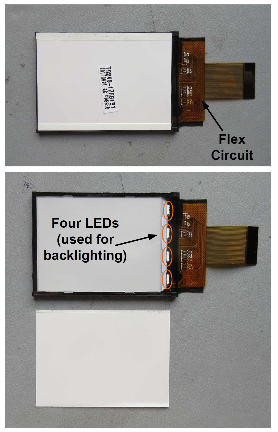
The LCD screen uses four LED for backlighting
The PCB
It's obvious that a mechanical engineer/designer was involved with the layout of the PCB given its particular shape. The various holes and slots used for securing the board to the enclosure, and the associated PCB keepout areas.The PCB layout person did an excellent job in laying out this board by 1) keeping all the components on one side of the PCB,and 2) keeping the board as a simple two-layer design (i.e., there's no internal layers). See the image below.
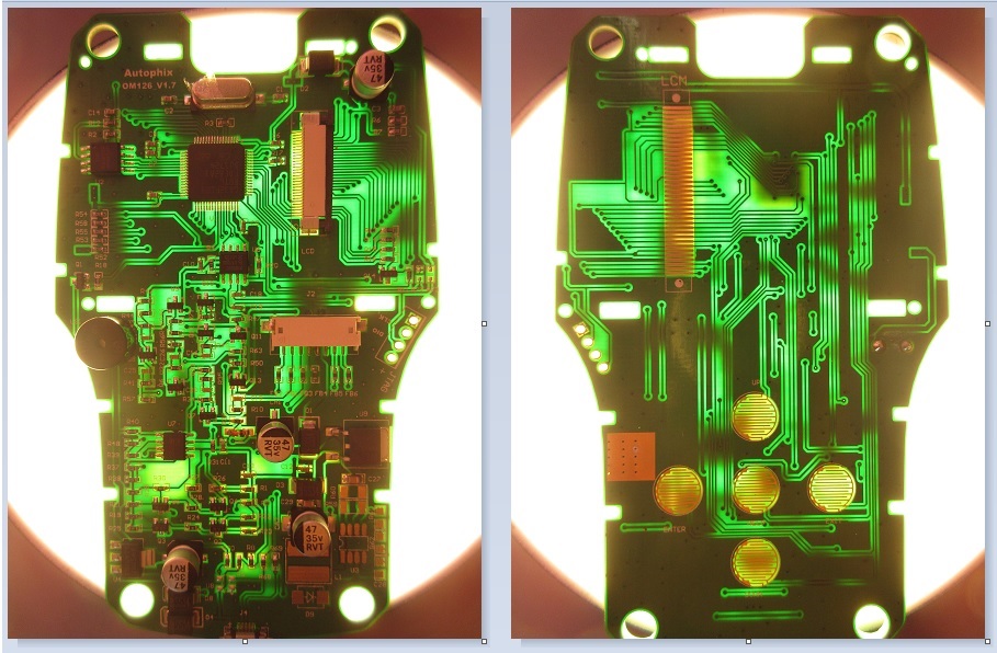
The PCB is a two-layer design—there are no internal layers. The PCB top side (left) and bottom side (right) held up to a light
The top side of the board is where all the components live, and this side of the PCB appears to use the HASL copper plating method, as identified by its tin-lead color.
The bottom side looks to employ either the ENIG or the hard gold copper plating method. These higher-end, more robust, and more expensive plating methods are necessary on the PCB's bottom side due to the high-wear areas of the push buttons. See the images below.
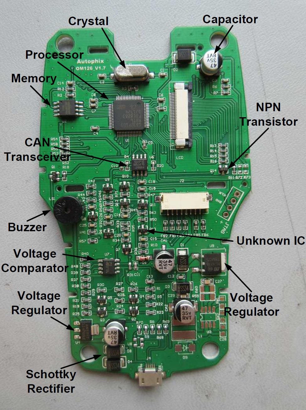
All components are located on the top side of the PCB. Click to enlarge.
- Crystal: Part marking: 8.000 (no datasheet)
- Capacitor (qty 4): Part marking: 47 35V RVT
- NPN Transistor (qty 11): Part marking: 1AM
- Unknown IC (qty 3): Part marking: 2A (no datasheet)
- Voltage Regulator: Part marking: 78M05
- Schottky Rectifier (qty 4): Part marking: SS34
- Voltage Regulator: Part marking: AMS1117
- Voltage Comparator: Part marking: ST 393
- Buzzer: Part marking: HXD (no datasheet)
- CAN Transceiver: NXP A1050/C
- Memory (Serial Flash): Part marking: 25Q128FVSG
- Processor (ARM): Part marking: GD32F103

No components are located on the PCB's bottom side
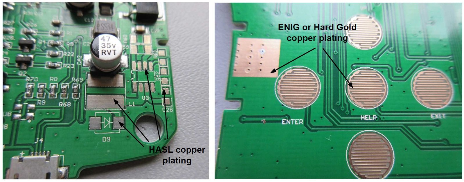
The PCB's top side (left) and bottom side (right) use different copper plating methods
Conclusion
This AD410 vehicle code reader looks to be a simple yet well-designed and well-constructed device. The use of the more robust copper plating on the PCB's bottom side should allow the push buttons to function properly for many years of service, and the two hard plastic enclosure pieces, together with the LCD's plastic cover, should protect the device from almost certain, though hopefully accidental, drops on the garage floor or driveway.Featured image courtesy of Amazon.


No comments:
Post a Comment