


There are various electrical signals in
nature are analog, that means a quantity change directly with another
quantity. Where the first quantity is voltage while another quantity can
be anything like force, temperature, light accelerations and pressure.
For instance, in IC LM35 temperature sensor
the o/p voltage changes depending on the temperature, so if we could
measure voltage, we can calculate the temperature. But, most of the
microcontrollers are digital in nature. They can only distinguish
between low or high level on i/p pins.
For example, if i/p is greater than 2.5v
then it will be read as high (1) and it is less than 2.5v then it will
be read as low (0). So we cannot directly measure voltage from
microcontrollers. To rectify this problem most of the microcontrollers
have analog to digital converter
unit which will convert from a voltage to a number so that it can be
handled by a digital system like microcontrollers. This allows us to
interface all types of analog devices with microcontroller unit. Some
examples of an analog devices are temperature, light, touch,
accelerometer and microphone for recording of audio. Please follow the
following link for : Types of analog and digital sensors with applications.
ADC in PIC Microcontroller
Analog to Digital Converter in PIC Microcontroller
Analog to digital converter in PIC microcontroller is discussed below.
PIC Microcontroller
The term PIC stands for programmable
interface controllers, which can be pre programmed to carry out a huge
variety of tasks. The production line can be controlled by a
preprogrammed microcontroller with timers.
The applications of PIC microcontrollers mainly involve in various
electronic devices like electronic gadgets, computer control systems,
alarm systems.
PIC Microcontroller
Different types of PIC microcontrollers
exist, while the finest are probably found in the GENIE range of
programmable microcontrollers. PIC microcontrollers are programmed
and replicated by circuit wizard software. These microcontrollers are
somewhat inexpensive and can be bought as kits or pre-built circuits
that can be designed by the user.
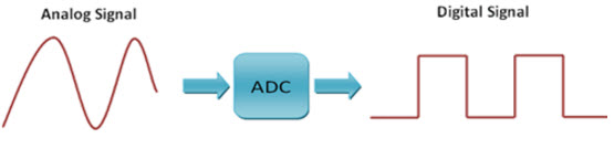
Analog to Digital Conversion
Analog to digital converter is essential in an embedded system
because, while these systems deal with digital values, their surrounds
usually involve various analog signals. These signals need to be changed
into digital before being treated by the microcontroller. Currently, we
can see how to read an exterior analog signal using PIC microcontroller
and display the digital output conversion on an LCD display. The input signal will be a changing voltage between 0 to 5v.
Analog to Digital Conversion
The most important specification of
analog to digital converter is the resolution. This specifies how
exactly the ADC measures the analog i/p signals. The common ADCs
available in the market are 8-bit, 10-bit and 12-bit. For instance, the
reference voltage of ADC is 0-5 volts, then a 8-bit analog to digital
converter will break this voltage into 256 parts. So it can calculate it
exactly up to 5/256v= 19mV approx. While the 10-bit analog to digital
converter will break the voltage into 1024parts. So it can calculate it
exactly up to 5/1024= 4.8 mV approx.. So you can observe that the 8-bit
ADC cannot tell the variation between 1mV & 18mV. The analog to
digital converter in PIC microcontroller are 10-bit.
The other specification of the ADC is
the sampling rate, that specifies how fast the A/D converter can take
readings. Microchip claims the ADC of the PIC can go high as 100k
samples/Sec.
ADC in PIC Microcontroller
Analog to digital conversion module in
PIC microcontroller usually has 5-i/ps for 28-pin devices and also
8-i/ps for 40-pin devices. The change of analog signal to the PIC , ADC
module effects in equivalent 10-bit digital number. The ADC module with
microcontroller has a software selectable low and high voltage reference
i/p to some combination of VSS, VDD, RA2 & RA3. In the following
project we will convert analog input to digital number with high voltage
reference and low voltage reference. The o/p will be shown using LEDs.
You can alter the reference voltages by arranging the ADCON1 register.
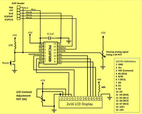
Circuit Diagram of ADC in PIC Microcontroller
The circuit diagram of the 10-bit analog
to digital converter using PIC microcontroller is shown below. The test
i/p voltage of ADC is received from a 5k potentiometer connected across
the potentiometer, and it connects to the two pins (AN2/RA2) of the PIC
microcontroller.The power supply
is selected as the reference voltage for analog to digital conversion.
Thus, the 10-bit A/D converter will change any analog voltage to a
digital. The output will be displayed on the LCD display.
Circuit Diagram of ADC in PIC Microcontroller
Software Required
The programming of A/D conversion in PIC microcontroller includes arranging the registers like ADCON0, ADCON1 and ANSEL.
- ADCON0 register is used to choose the analog i/p channel, start the conversion and to check the conversion is completed or not and also switch ON/OFF the module.
- ADCON1 register is used to choose voltage reference, and to arrange ports as an analog to digital
- ADCON2 register is used to choose the A/D data format, fix a acquisition time, A/D clock setup.
As an analog input AN2/RA2 is used, the
equivalent ANSEL register must be fixed. In register ADCON0, clear HS0
& CHS2 and set CHS1, so that the channel AN2 will be associated with
the internal S&H circuit (sample and hold circuit).
In the ADCON1 register, clearing the VCFG bit will choose the voltage
supply for analog to digital conversion. This register is used to select
the CLK source in analog to digital conversion. Though, the MikroC Pro
for microcontroller has got a built in library function termed as
ADC_Read (), by default, uses the internal RC CLK for ADC operation.So
no need to reset the ADCON1 register.
Thus, this is all about analog to
digital converter in PIC microcontroller, which includes what is a PIC
microcontroller, analog to digital converter, ADC in PIC microcontroller
and the required software. We hope that you have got a better
understanding of this concept. Furthermore, any queries regarding this
concept or PIC Microcontroller Projects or electrical and electronic projects,
please give your valuable suggestions by commenting in the comment
section below.Here is a question for you, what are the applications of
analog to digital converter?


No comments:
Post a Comment