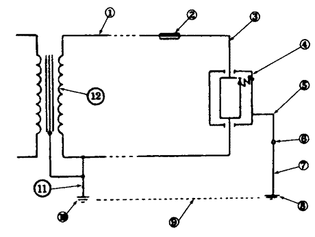
The path followed by fault current as the
result of a low impedance occurring between the
phase conductor and earthed metal is called the earth fault
loop. Current is driven through the loop impedance
by the supply voltage.
The extent of the earth fault loop for
a TT system is shown in {Fig 5.7}, and is made up of the
following labelled parts.
 |
Fig 5.7 The earth fault
loop
l. - the phase conductor from the
transformer to the installation
2.
- the protective device(s) in the installation
3.
- the installation phase conductors from the intake
position to the fault
4. - the fault itself (usually assumed
to have zero impedance)
5. - the protective conductor system
6. - the main earthing terminal
7. - the earthing conductor
8. - the installation earth electrode
9. - the general mass of earth
10. - the Supply Company's earth
electrode
11. - the Supply Company's earthing
conductor
12.
- the secondary winding of the supply transformer
For a TN-S system (where the Electricity
Supply Company provides an earth terminal), items 8 to 10
are replaced by the PE conductor, which usually takes the
form of the armouring (and sheath if there is one) of the
underground supply cable.
For a TN-C-S system (protective multiple
earthing) items 8 to 11 are replaced by the combined neutral
and earth conductor.
For a TN-C system (earthed concentric wiring),
items 5 to 11 are replaced by the combined neutral and earth
wiring of both the installation and of the supply.
It is readily apparent that the impedance
of the loop will probably be a good deal higher for the
TT system, where the loop includes the resistance of two
earth electrodes as well as an earth path, than for the
other methods where the complete loop consists of metallic
conductors.


No comments:
Post a Comment