


A robot can be controlled wirelessly in many different ways. The wireless control for a robotic vehicle can be implemented via Bluetooth, Wi-Fi or RF. A wireless robot controlled over Bluetooth can have HC-05 Bluetooth module interfaced in its circuit by which it can pair with any other Bluetooth device. The same way, a Wi-Fi controlled robot can have ESP8266 Wi-Fi module interfaced in its circuit to connect to a remote server via Wi-Fi hotspot or to connect to a device via Wi-Fi tethering. An RF-based wireless robot has an RF receiver interfaced in its circuit to which control commands can be passed through an RF transmitter. The RF transmitter can be part of a remote control or interfaced to a PC via a controller circuit.
In this tutorial, a wireless robot controlled over RF interface is designed. The RF transmitter is interfaced to a computer via controller circuit based on Arduino UNO. the computer runs a Matlab based application which controls the movement of the robot. So the motion of the robot is wirelessly controlled through a Matlab based GUI. The RF module used in the project is 433 MHz RF module. It has a typical range of 50 to 60 metre which can be extended up to 300 Metre by using antenna and proper transmission power.
For designing this robotic system, a Matlab GUI is designed on computer and an Arduino Sketch which can receive command characters serially from the computer and transmit motor control logic accordingly are designed. The robot itself houses a RF receiver circuit which is capable of implementing DC motor control without use of any additional controller. The Arduino sketch is written and compiled using Arduino IDE while the GUI is designed within the Matlab platform.

Matlab GUI controlled RF Robot
Components Required -

Block Diagram -
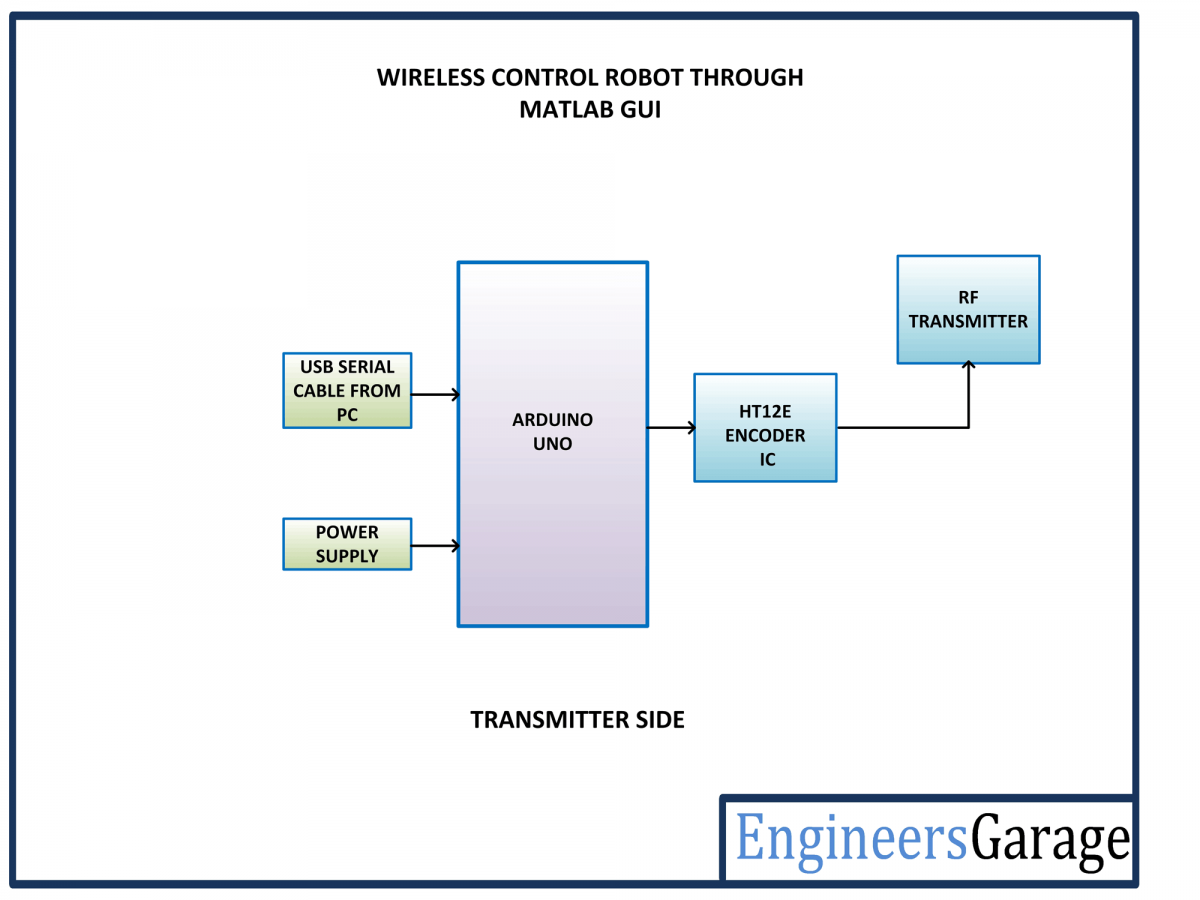
Matlab GUI controlled RF Robot Transmitter Side Building Blocks
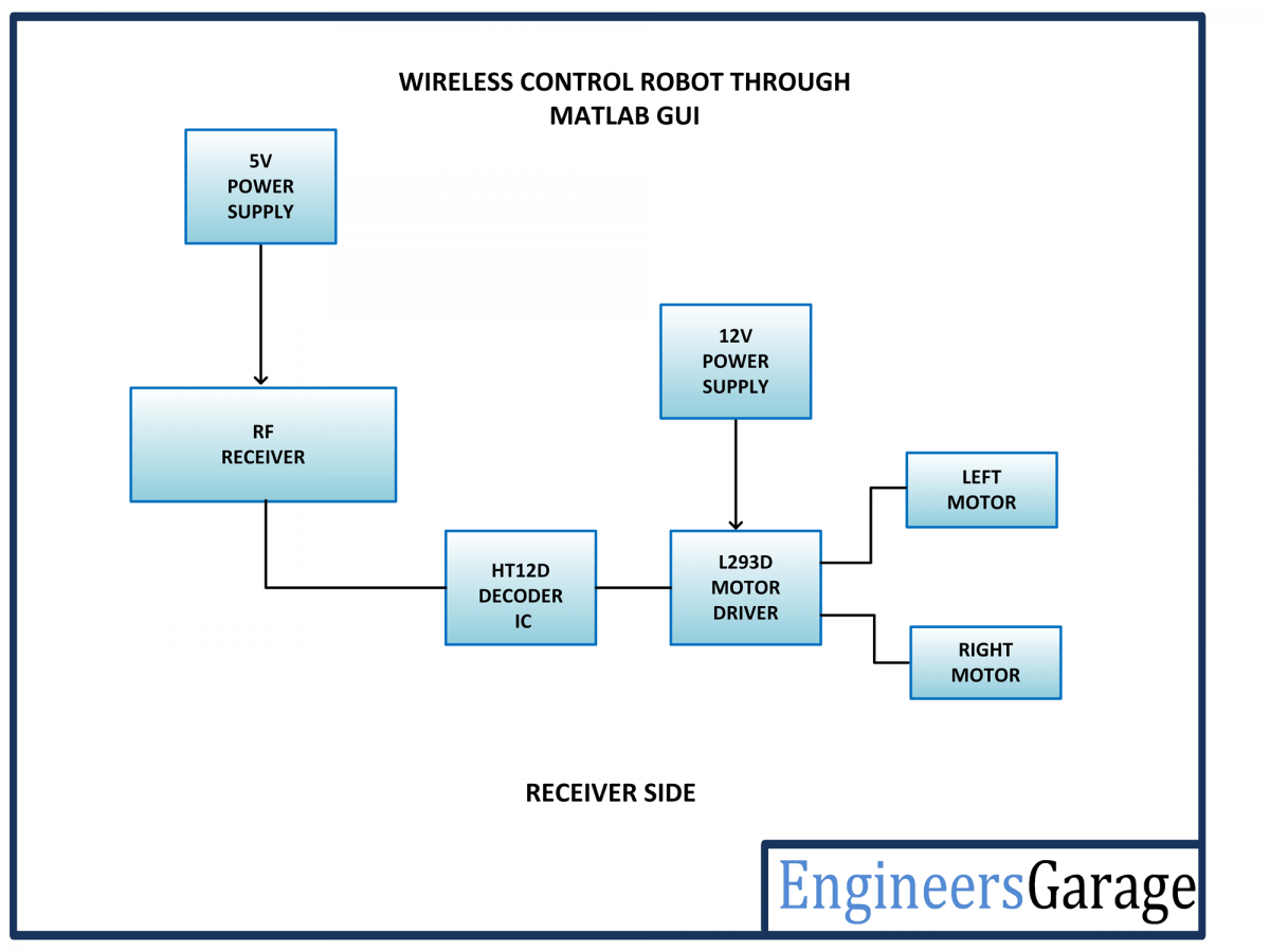
Matlab GUI controlled RF Robot Receiver Side Building Blocks
Circuit Connections -
There are two circuits designed in this robotic project - one is the transmitter circuit which is basically a controller based RF transmitter connected to a PC through serial interface and other is receiver circuit mounted on the robot which controls the motor driver IC.

Matlab GUI controlled RF Robot Transmitter Side Circuit
The transmitter circuit is built by assembling the following circuit sections -
Arduino UNO - Arduino UNO is one of the most popular prototyping boards. It is used frequently in robotic applications as it is small in size and packed with rich features. The board comes with built-in arduino boot loader. It is an Atmega 328 based controller board which has 14 GPIO pins, 6 PWM pins, 6 Analog inputs and on board UART, SPI and TWI interfaces. In this project, the Arduino board is connected to a PC via USB port and 4 GPIO pins of the board are utilized to interface HT12E RF encoder IC with it.
RF Transmitter - The RF transmitter is used to transmit the input signals for motor control. The RF transmitter module is a small PCB sub assembly. The RF module, as the name suggests, operates at Radio Frequency. The corresponding frequency range varies between 30 kHz & 300 GHz. In this RF system, the digital data is represented as variations in the amplitude of carrier wave. This kind of modulation is known as Amplitude Shift Keying (ASK). This RF module operates over 433 MHz frequency and uses ASK modulation technique. The pin configuration of transmitter module is as follows-

The serialized data from the encoder is received at pin 2 of the module and passed onto the antenna from pin 4 of the module.
HT12E IC - The HT12E IC converts the parallel data into serial data for passing it to the RF transmitter. HT12E encoder IC belongs to the 212 series of encoders. It is paired with 212 series of decoders having the same number of addresses and data format. HT12E is capable of encoding 12 bits, out of them 8 are address bits and 4 are data bits. Thus the encoded signal is a serialized 12-bit parallel data comprising of 4-bit data to be transferred appended with the address byte.
The data pins D0, D1, D2, and D3 of the IC are connected to the pins 2, 3, 7 and 8 of the Arduino board respectively. All the address pins of the encoder IC are hardwired to ground, so it has an address byte of 0x00. The pin 17 of the IC is connected to pin 2 of the RF transmitter. So, the serialized data is passed from pin 2 of the IC to data input pin of the RF transmitter.
HT12E has a transmission enable pin which is active low. When a trigger signal is received on TE pin, the programmed addresses/data are transmitted together with the header bits via an RF or an infrared transmission medium. HT12E begins a 4-word transmission cycle upon receipt of a transmission enable. This cycle is repeated as long as TE is kept low. As soon as TE returns to high, the encoder output completes its final cycle and then stops.
Power Supply - The Arduino board draws power from the USB interface itself. The VCC and ground pins of the RF transmitter and the encoder IC are connected to the common VCC and ground respectively.
The receiver circuit is built by assembling the following components together -

Matlab GUI controlled RF Robot Receiver Side Circuit
RF Receiver - The RF receiver detects the radio signal carrying the motor control signals. The RF receiver module has 8 pins and has following pin configuration -

The RF receiver passes the serial data received over RF frequency from its pin 2 to pin 16 of the decoder IC.
HT12D Decoder - The signal detected from the RF receiver is passed to the HT12D decoder. It converts the serial data back to the parallel data after separating data and addresses. HT12D belongs to the 212 series of decoders and can be paired with 212 series of encoders having the same number of addresses and data format. HT12D is capable of decoding 12 bits, out of them 8 are address bits and 4 are data bits. The 4-bit data is of latch type and when passed to the output data pins it remains unchanged until the new data is received.
The serial data received by the RF receiver is parallel output from its data pins as it is. The data pins of the decoder IC are interfaced with input pins of the L293D motor driver IC. So the digital logic at the data pins of the decoder control the rotation of the DC motors. All the address pins of the decoder IC are connected to ground to match the address byte to 0x00 same as of the transmitter circuit.
L293D DC Motor Driver IC- The L293D is a dual H-bridge motor driver integrated circuit (IC). The Motor drivers act as current amplifiers since they take a low-current control signal and provide a higher-current signal. This higher current signal is used to drive the motors. It has 16 pins with following pin configuration:
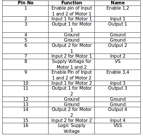
There are two DC motors used for making the robotic car. The DC motors are interfaced between pins 3 and 6 and pins 14 and 11 of the motor driver IC.
The L293D IC controls the DC Motors according to the following truth tables:


The pin 4, 5, 13 and 12 of the L293D are grounded while pin 1, 16 and 9 are connected to 5V DC and pin 8 is connected to 12V DC. The pins 15, 2, 7 and 10 of the motor driver IC are connected to pins 8, 2, 3 and 7 of the Arduino board. The DC motor attached to right wheel is connected to pins 11 and 14 while motor attached to left wheel is connected to pins 3 and 6 of the motor driver IC.
Geared DC Motors - In this robot, 12V geared DC motors are attached to the wheels. Geared DC motors are available with wide range of RPM and Torque, which allow a robot to move based on the control signal it receives from the motor driver IC.
Power Supply - In the circuit, RF transmitter and decoder IC need a 5V regulated DC for their operation while the motor driver IC needs 12V DC. A 12V NIMH battery is used as the primary source of power. The supply from the battery is regulated to 5V and 12V using 7805 and 7812 ICs. The pin 1 of both the voltage regulator ICs is connected to the anode of the battery and pin 2 of both ICs is connected to ground.
The respective voltage outputs are drawn from pin 3 of the respective voltage regulator ICs. An LED along with a 10K Ω pull-up resistor is also connected between common ground and output pin to get a visual hint of supply continuity. Despite using 12V battery, 7812 is used to provide a regulated and stable supply to the motor driver IC.
How the circuit works -
As the battery is attached to the robot, the RF receiver is configured to pair with the RF transmitter and start receiving the data. On the transmitter side, the arduino board must be connected to the PC via USB cable and the Matlab based GUI must be launched to realize the application. The GUI has directional buttons given to move the robot in forward, backward, left and right direction. On pressing a button, specific string command is passed to the Arduino board. The following strings are passed to transfer the control commands from the Matlab GUI -

The Arduino sketch running on the Arduino UNO receives the command strings serially through virtual serial communication. Each string command is tested in decision making statements and appropriate motor control signals are passed at the controller pins connected to the data pins of the decoder IC. The same digital logic is reflected at the data pins of the encoder IC as it is. The robot can be moved forward, backward, left or right by implementing the following input logic at the motor driver pins -

Check out the programming guide to learn how the Matlab GUI has been designed. Read through the Arduino sketch to learn how serially received command strings are detected and interpreted to change input control signals for the motor driver IC.
Programming Guide -
GUIs (also known as graphical user interfaces or UIs) provide point-and-click control of software applications, eliminating the need to learn a language or type commands in order to run the application. MATLAB apps are self-contained MATLAB programs with GUI front ends that automate a task or calculation. The GUI typically contains controls such as menus, toolbars, buttons, and sliders. Many MATLAB products, such as Curve Fitting Toolbox, Signal Processing Toolbox, and Control System Toolbox include apps with custom user interfaces. One can also create custom apps that include UI for others to use.
The project's functioning is performed by the software program loaded into the internal memory of Arduino board. The program implements all required functionalities including user inputs through MATLAB GUI interface. The designing of GUI as well as Arduino sketch can be understood in the following steps -
1. Arduino IDE 1.6.5 is used for programming Arduino Uno. The latest IDE can be downloaded from Arduino’s official website. After downloading Arduino IDE, install it. Note the directory of Arduino IDE installation.
2. Download Legacy MATLAB and Simulink Support for Arduino package from MathWorks website. Extract the compressed folder named ArduinoIO. From this folder, copy pde folder and paste it in C:\Program Files (or Program files x86)\Arduino\Libraries (path may be different depending on the installation directory of the IDE).
After pasting pde folder in correct location, open Arduino IDE. If the file is pasted in correct location, one would find pde in File → Examples → pde. Open the code by File→ Examples → pde → adioes.
3. Connect Arduino Uno board to the PC. From Device Manager, note the COM port at which Arduino Uno board is installed. From Tools menu in Arduino IDE, select the board as Arduino Uno and select the COM Port number noted earlier. Upload adioes code to Arduino Uno board by pressing Upload button in the IDE.
4. Copy the entire contents of the extracted ArduinoIO folder to a folder in My Documents (For Windows PC).
5. The application program has been developed in R2008a version of MATLAB. After installing this version of MATLAB in the PC, open install_arduino.m file present in the directory where one has copied the contents of ArduinoIO folder. Now, run install_arduino.m file. This code will correctly install and save the path of Arduino support package.
6. Once done with the above procedure, creating a GUI involves the few steps. Just type guide in the command window of the MATLAB, there will be a popup window (GUIDE quick start) with options. Select or click on the Blank GUI (Default) to create a new GUI.
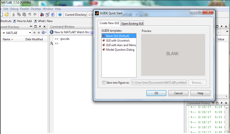
Matlab GUI Guide
7. The new window to create GUI appears, on the left side where one can find many options to create buttons, text box, sliders and much more. Click on the push button and draw on the editor window. Once done double click on the button and there one can edit button name.
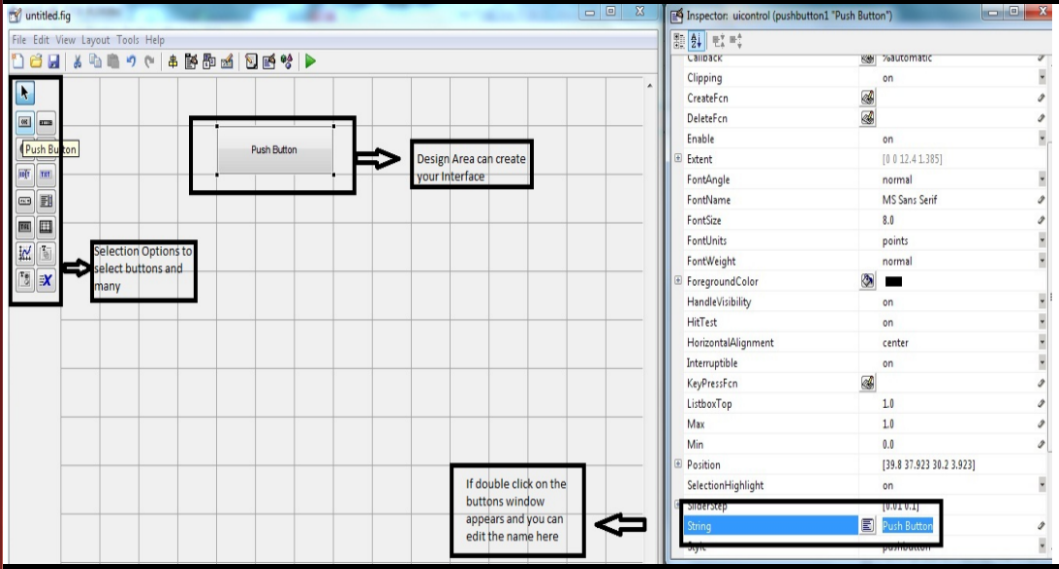
Designing Matlab UI Elements
8. One can design the GUI depending on the application and desired UI appearance. This GUI designed for controlling the Robot looks as shown below -

Matlab GUI for Robot Control
9. After designing the GUI save it and once saved a window appears with some body of codes where one can edit the robot control code in it.
The window appears like as the image as shown below.

ArduinoIO Program Generated from Matlab GUI
10. From the image shown below declare the COM PORT number (serial port) in which one has connected the arduino to the PC, after that declare pin modes as (a.pinMode (5, Output)), which defines the serial port connected to the arduino board.

ArduinoIO Program Generated from Matlab GUI and modifications in it
Check out the attached code for more details.


No comments:
Post a Comment