


This is part 3 of a series of articles on my experiences building a robot that can do various things. I thought it would be neat to create a robot that was easy to put together with a single soldering iron and was also affordable. I made up the following requirements for my robot:
- Many kits are expensive, so it must be relatively inexpensive.
- It must be easily put together without special equipment.
- It must be easily programmable without a complicated IDE or programmer.
- It must be powerful enough for expandability.
- It should run off a simple power source.
- It should be able to follow a line or a wall, and avoid obstacles.
Gathering the Components
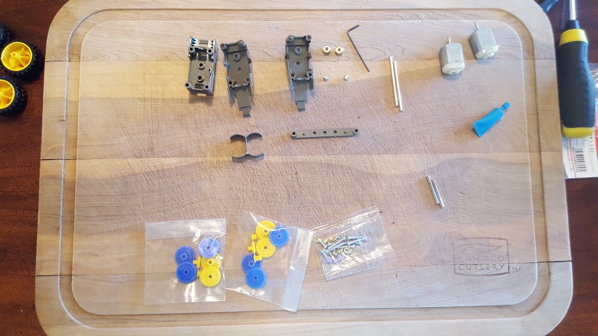
I ordered all of the components, which all came in a reasonably fast amount of time. Here they are laid out ready to be assembled.
Assembling the Mechanical Components
Ball Caster
The ball caster came as a kit that had to be assembled. It offered a variety of size options. It wasn't too difficult so I didn't take any pictures of the assembly process.Motor
The motor also came as a kit and was much more complicated. The motor kit offers 4 different gear ratios. I ended up choosing 38:1 for the great ratio because I didn't want the robot to be too slow but still handle pulling the weight around. The higher gear ratios would have been an unneccessary amount of torque. The only real weight on the robot is the batteries. The gear ratio can always be adjusted after assembly, but it would be a bit of a pain. The motor speed can be adjusted by altering the PWM duty cycle to the motor controller, so if the gear ratio produced too high of a speed it can be lowered with software.Here are all of the various pieces from the kit. I used a cutting board for assembly because the small screws have a habit of rolling off the table.
The fully assembled robot motor and gears. The kit came with everything required, including grease. The only tool I needed was a screw driver.

Attached to the PCB, it actually lines up with the silk screen nicely!

Soldering the Components
I used female headers in case I wanted to swap out the components later. Soldering all of the male headers to the DIP break-out boards was a bit tedious, but much easier than soldering all of the surface mount components would have been! I had to use a bunch of headers connected together to get the line sensor to be close enough to the ground to be affective. If I started from scratch I'd prefer a cleaner way of mounting the line sensor.
Testing the Motors
At first I just connected the motors directly to the 2AA batteries to see if the gears were properly greased. I also measured the current to make sure it was in spec. After proving the motors could be turned forwards and reverse, I connected them to the motor driver. I wrote some test software that ran the motors forwards and backwards for five seconds. This proved out the connections between the Teensy, the motor controller, and the motor all at once. It's a pleasing result when you don't have to troubleshoot connections on a first revision PCB! The following code drives the robot forwards for 5 seconds at about half power, and then backwards for 5 seconds. I wrote a driver called "robot.ino" that takes care of turns and sensor reading. See the end of the article for the driver. To program the Teensy, download the Teensyduino add-on for the Arduino platform. Programming is then exactly the same as using an Arduino.I used a jumper as an on/off switch during testing.

It's alive!
                    #include "robot.h"

void setup()
{
  Serial.begin(38400);
  Serial.println("Boot");
  rbt_init();
  rbt_move(FWD,100);
  delay(5000);
  rbt_move(REV,100);
  delay(5000);
  rbt_move(BRAKE,0);
}

void loop()
{
}
Testing the Sensors
To test the sensors I wrote a program that printed the raw value from the sensors. I found out that I couldn't use the wall sensors at the same time or they would all activate 100% of the time. The reason for this is that the IR receivers have a wide angle and they pick up the signals from adjacent transmitters. I wrote the library so that it alternates reading each sensor by taking advantage of the enable pin on the sensor. The wall sensors also have to be angled up a little bit, or they pick up the ground as an object.The sensor reading function executes in 1ms, offering 1kHz speed to handle fairly complex control algorithms if needed. The test code also demonstrated that the line sensor has to be very close to the ground to effectively determine the difference between colors. If the robot is a couple inches off the ground, the line sensors max out at a reading of 1000. This actually can be useful to make the robot stop moving when being carried around.
Line sensor very close to ground, but not touching!

                    #include "robot.h"

void setup()
{
  Serial.begin(38400);
  Serial.println("Boot");
  rbt_init();
}

uint16_t lleft,lmid,lright;
boolean wleft,wmid,wright;
void loop()
{
  rbt_sns(&lleft,&lmid,&lright,&wleft,&wmid,&wright);
  Serial.print("Line left: ");
  Serial.print(lleft);
  Serial.print("Line mid: ");
  Serial.print(lmid);
  Serial.print("Line right: ");
  Serial.print(lright);
  Serial.print("Wall left: ");
  Serial.print(wleft);
  Serial.print("Wall mid: ");
  Serial.print(wmid);
  Serial.print("Wall right: ");
  Serial.println(wright);
}
Conclusion
In this article I showed the process of assembling a robot and testing the components individually. It's important to do this when you first get boards, because you never know what mistakes might have been made in the design or the manufacture of the PCB. If you jump right in to the application design, you might miss something that causes problems down the road. In the next article I'll talk about how to turn the robot into a line follower by righting a simple algorithm to stay centered on a black line.Robot Library
robot.h
                    #ifndef _ROBOT_H
#define _ROBOT_H

#include "Arduino.h"

/*DRV8835*/
const int BPHASE = 5;
const int APHASE = 3;
const int AEN = 4;
const int BEN = 6;
const int DRV_MODE = 2;
#define MOTOR_REV  LOW
#define MOTOR_FWD  HIGH

/*reflection sensor interface*/
const int OUT1 = 33;
const int OUT2 = 32;
const int OUT3 = 31;

/*wall sensor interface*/
const int WALL_LEFT_EN = 15;
const int WALL_LEFT = 14;
const int WALL_RIGHT_EN = 19;
const int WALL_RIGHT = 18;
const int WALL_MID_EN = 17;
const int WALL_MID = 16;

/*robot interface*/
typedef enum{
  LEFT,
  RIGHT,
  FWD,
  REV,
  BRAKE,
}direction_t;

void rbt_move(direction_t new_dir, uint8_t speed);
void rbt_sns( uint16_t *line_left,
              uint16_t *line_mid,
              uint16_t *line_right,
              boolean  *wall_left,
              boolean  *wall_mid,
              boolean  *wall_right);
void rbt_init();

#endif /*_ROBOT_H*/
robot.ino
                    #include "robot.h"

void rbt_init()
{
  pinMode(BPHASE, OUTPUT);
  pinMode(APHASE, OUTPUT);
  pinMode(AEN, OUTPUT);
  pinMode(BEN, OUTPUT);
  pinMode(DRV_MODE, OUTPUT);
  pinMode(WALL_LEFT_EN, OUTPUT);
  pinMode(WALL_MID_EN, OUTPUT);
  pinMode(WALL_RIGHT_EN, OUTPUT);
  pinMode(WALL_LEFT, INPUT);
  pinMode(WALL_MID, INPUT);
  pinMode(WALL_RIGHT, INPUT);
  digitalWrite(WALL_LEFT_EN,LOW);
  digitalWrite(WALL_MID_EN,LOW);
  digitalWrite(WALL_RIGHT_EN,LOW);
    /*simplified drive mode*/
  digitalWrite(DRV_MODE, HIGH);
}

void rbt_move(direction_t new_dir, uint8_t speed)
{
  if(speed)
  {
    switch(new_dir){
      case LEFT:
        digitalWrite(BPHASE,MOTOR_FWD);
        digitalWrite(APHASE,MOTOR_FWD);
        analogWrite(AEN,speed);
        analogWrite(BEN,speed-speed/2);
        break;
      case RIGHT:
        digitalWrite(BPHASE,MOTOR_FWD);
        digitalWrite(APHASE,MOTOR_FWD);
        analogWrite(AEN,speed-speed/2);
        analogWrite(BEN,speed);
        break;
      case FWD:
        digitalWrite(BPHASE,MOTOR_FWD);
        digitalWrite(APHASE,MOTOR_FWD);
        analogWrite(AEN,speed);
        analogWrite(BEN,speed);
        break;
      case REV:
        digitalWrite(BPHASE,MOTOR_REV);
        digitalWrite(APHASE,MOTOR_REV);
        analogWrite(AEN,speed);
        analogWrite(BEN,speed);
        break;
      default:
          analogWrite(AEN,0);
          analogWrite(BEN,0);
          break;
    }
  }
  else
  {
    analogWrite(AEN,0);
    analogWrite(BEN,0);
  }
}

/*function takes 1ms to run*/
#define LOOP_ITER_CNT 2
void rbt_sns( uint16_t *line_left,
              uint16_t *line_mid,
              uint16_t *line_right,
              boolean  *wall_left,
              boolean  *wall_mid,
              boolean  *wall_right)
{
  *line_left=0;
  *line_mid=0;
  *line_right=0;
  uint16_t usec_timer=0;
  /*line sensor*/
  /*charge lines*/
  pinMode(OUT1, OUTPUT);
  pinMode(OUT2, OUTPUT);
  pinMode(OUT3, OUTPUT);
  digitalWrite(OUT1,HIGH);
  digitalWrite(OUT2,HIGH);
  digitalWrite(OUT3,HIGH);
  delayMicroseconds(3);
  /*set to Hi-Z to let cap discharge*/
  pinMode(OUT1, INPUT);
  pinMode(OUT2, INPUT);
  pinMode(OUT3, INPUT);
  /*enable first wall sensor*/
  digitalWrite(WALL_LEFT_EN,HIGH);
  while(1){
    /*each loop is about 2us at 48MHz*/
    usec_timer+=LOOP_ITER_CNT;
    /*increment counts for line sensors every us to track the decay of the capacitor*/
    if(digitalRead(OUT1) == 1)
    {
      (*line_left)+=LOOP_ITER_CNT;
    }
    if(digitalRead(OUT2) == 1)
    {
      (*line_mid)+=LOOP_ITER_CNT;
    }
    if(digitalRead(OUT3) == 1)
    {
      (*line_right)+=LOOP_ITER_CNT;
    }
    /*take turns reading wall sensors because they interfere with each other*/
    if(usec_timer == 300)
    {
      *wall_left = (digitalRead(WALL_LEFT) ? false:true);
      digitalWrite(WALL_LEFT_EN,LOW);
    }
    if(usec_timer == 400)
    {
      digitalWrite(WALL_MID_EN,HIGH);
    }
    if(usec_timer == 700)
    {
      *wall_mid = (digitalRead(WALL_MID) ? false:true);
      digitalWrite(WALL_MID_EN,LOW);
    }
    if(usec_timer == 700)
    {
      digitalWrite(WALL_RIGHT_EN,HIGH);
    }
    if(usec_timer>=1000)
    {
      *wall_right = (digitalRead(WALL_RIGHT) ? false:true);
      digitalWrite(WALL_MID_EN,LOW);
      return;
    }
  }
}


No comments:
Post a Comment