


Multi-vibrator circuits refer to the special type of electronic circuits
used for generating pulse signals. These pulse signals can be
rectangular or square wave signals. They generally produce output in two
states: high or low. A specific characteristic of multi-vibrators is
the use of passive elements like resistor and capacitor to determine the
output state.
Multivibrator Circuits
Types of Multi-Vibrators
a. Monostable Multi-vibrator:
A monostable multivibrator is the type of multivibrator circuit whose
output is in only one stable state. It is also known as one-shot
multivibrator. In a monostable multivibrator, the output pulse duration
is determined by the RC time constant and is given as: 1.11*R*C
b. A Stable Multi-vibrator:
A stable vibrator is a circuit with an oscillating output. It doesn’t
need any external triggering, and it has got no stable state. It is a
type of regenerative oscillator.
c. Bistable Multi-vibrator:
A bistable vibrator is a circuit with two stable states: high and low.
Generally a switch is required for toggling between the high and low
state of the output.
Three Types of Multi-vibrator Circuits
1. Using Transistors
a. Monostable Multi-vibrator
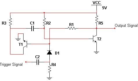
Monostable Multi-vibrator Circuit
In the above circuit, in absence of any
external trigger signal, the base of the transistor T1 is at the ground
level and the collector is at a higher potential. Therefore, the
transistor is cut off. However, the base of the transistor T2 gets
positive voltage supply from the VCC through a resistor, and the
transistor T2 is driven to saturation. And, as the output pin is
connected to the ground through the T2, it is at logic low level.
When a trigger signal is applied to the
base of the transistor T1, it starts conducting as its base current
increases. As the transistor conducts, its collector voltage decreases.
At the same time, the capacitor C2’s voltage starts discharging through
the T1. This causes the potential at the base terminal of the T2 to
decrease and eventually the T2 is cut off. Since the output pin is now
directly connected to a positive supply through resistor: Vout is at
logic high level.
After sometime, when the capacitor is
discharged completely, it starts charging up through the resistor. The
potential at the base terminal of transistor T2 starts increasing
gradually and eventually the T2 is driven to conduction. Thus, the
output is again at a logic low level or the circuit is back to its
stable state.
b. Bistable Multivibrator
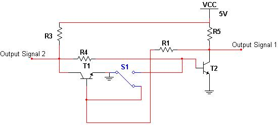
Bistable Multivibrator Circuit
The above circuit is a bistable multivibrator circuit with two outputs, defining the two stable states of the circuit.
Initially, when the switch is at the
position A, the base of transistor T1 is at the ground potential, and
therefore, it is cut off. At the same time, the base of transistor T2 is
at a comparatively higher potential, it starts conducting. This causes
output pin 1 to be directly connected to the ground, and the Vout1 to be
at logic low level. The output pin2 at the collector of T1 is
connected directly to the Vcc, and the Vout2 is at logic high level.
Now, when the switch is at position B,
the transistor actions are reversed (T1 is conducting and T2 is cut off)
and the output states are reversed.
c. Astable Multivibrator
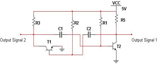
Astable Multivibrator Circuit
The above circuit is an oscillator
circuit. Suppose, initially the transistor T1 is in conduction and T2 is
in cut off. The output 2 is at logic level, and the output 1 is at
logic low level. As the capacitor c2 starts charging up through R4, the
potential at the base of T2 starts increasing gradually until T2 starts
conducting. This decreases its collector potential and gradually the
potential at the base of T1 starts decreasing until it is completely cut
off.
Now, as C1 charges through R1, the
potential at the base of the transistor T1 starts increasing and
eventually it is driven to conduction, and the whole process repeats.
Thus, the output is constantly repeating or oscillating.
Apart from using BJTs, other types of transistors are also used in multi-vibrator circuits.
2. Using Logic Gates
a. Mono-Stable Multi-Vibrator
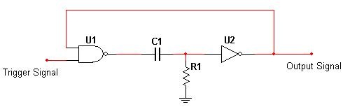
Mono-Stable Multi-Vibrator Circuit
Initially the potential across the
resistor is at ground level. This implies a low logic signal to the
input of the NOT gate. Thus, the output is at logic high level.
As both the inputs of NAND gate are at
logic high levels, the output is at logic low level, and the circuit
output remains in its stable state.
Now, suppose a logic low signal is given
to one of the inputs of the NAND gate, the other input being at logic
high level, the output of the gate is logic 1, i.e., positive voltage.
Since there is a potential difference across R, VR1 is at logic high
level, and accordingly the output of the NOT gate is logic 0. As this
logic low signal is fed back to the input of NAND gate, its output
remains at logic 1 and the capacitor voltage starts increasing
gradually. This in turn causes the potential drop across the resistor,
i.e., VR1 starts decreasing gradually and at one point it goes low, such
that a logic low signal is fed to the input of NOT gate, and the output
is again at logic high signal. The time period for which the output
remains in its stable state is determined by the RC time constant.
b. Astable Multi-vibrator
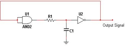
Astable Multi-vibrator Circuit
Initially, when the supply is given, the
capacitor is uncharged and a logic low signal is fed to the input of
the NOT gate. This causes the output to be at logic high level. As this
logic high signal is fed back to the AND gate, its output is at logic
1. The capacitor starts charging and the input level of the NOT gate
increases until it reaches the logic high threshold, and the output is
at logic low.
Again, the AND gate output is at logic
low (logic low input is being fed back), and the capacitor starts
discharging until its potential at input of the NOT gate reaches logic
low threshold, and the output is again switched back to the logic high.
This is actually a type of relaxation oscillator circuit.
c. Bistable Multi-vibrator
The simplest form of bistable multi-vibrator is the SR latch, realized by logic gates.
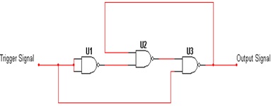
Bistable Multi-vibrator Circuit
Suppose the initial output is at a logic
high level (Set) and the input trigger signal is at a logic low signal
(Reset). This causes the output of NAND gate 1 to be at logic high
level. As both the inputs of U2 are at logic high level, the output is
at logic low level.
Since both the inputs of U3 are at a
logic high level, the output is at logic low level, i.e., Reset. The
same operation occurs for a logic high signal at the input, and the
circuit changes state between 0 and 1. As seen the use of logic gates
for multi-vibrators are actually examples of digital logic circuits.
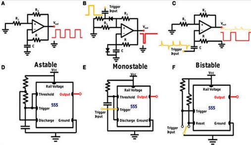
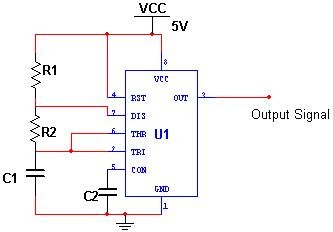
3. Using 555 Timers
555 Timer IC is the most commonly used IC for pulse generation, especially pulse width modulation, for multivibrator circuits.
a. Monostable Multi-vibrator
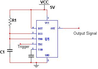
Monostable multi-vibrator Circuit
To connect a 555 timer in monostable
mode, a discharge capacitor is connected between the discharge pin 7 and
ground. The pulse width of the generated output is determined by the
value of the Resistor R between the discharge pin, Vcc and Capacitor C.
If you are aware of the internal circuitry of 555 timer, you must be aware of the fact that a 555 timer works with a transistor, two comparators and a SR flip-flop.
Initially, when the output is at logic
low signal, the transistor T is driven to conduction and pin 7 is
grounded. Suppose a logic low signal is applied to the trigger input or
the input of the comparator, as this voltage is less than 1/3Vcc, the
output of the comparator IC goes high, causing the flip-flop to reset
such that the output is now at a logic low level.
At the same time, the transistor is
switched off and the capacitor starts charging through Vcc. When the
capacitor voltage increases beyond 2/3Vcc, the comparator 2 output goes
high, causing the SR flip-flop to set. Thus, the output is again at its
stable state after a certain time period determined by the values of R
and C.
b. Astable Multivibrator
To connect a 555 timer in astable mode, the pins 2 and 6 are shortened and a resistor is connected between pin 6 and 7.
Astable Multivibrator Circuit
Initially, suppose the output of the SR
flip-flop is at a logic low level. This switches off the transistor and
the capacitor starts charging to Vcc through Ra and Rb in such a way
that, at one time, the input voltage to comparator 2 exceeds the
threshold voltage of 2/3Vcc, and the comparator output goes high. This
causes the SR flip-flop to set in such a way that the timer output is at
logic low.
Now, the transistor is driven to
saturation by a logic high signal at its base. The capacitor starts
discharging through Rb, and when this capacitor voltage falls below 1/3
Vcc, the output of the comparator C2 is at logic high level. This resets
the flip-flop and the timer output is again at logic high level.
c. Bi-stable Multi-vibrator
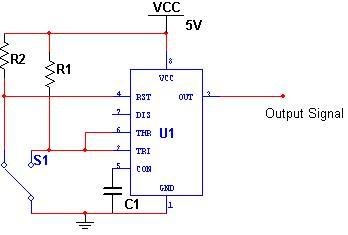
Bi-stable Multi-vibrator Circuit
A 555 timer in bi-stable multi-vibrator
doesn’t require the use of any capacitor; rather a SPDT switch is used
between ground and pins 2 and 4.
When the switch position is in such a
way that the pin 2 is at ground along with pin 6, the output of the
comparator 1 is at logic low signal, whereas the output of the
comparator 2 is at logic high signal. This resets the SR flip-flop, and
the output of the flip flop is logic low. The output of the timer is
thus logic high signal.
When the switch position is in such a
way that the pin 4, or the reset pin of the flip-flop is grounded, the
SR flip-flop is set, and the output is at logic high. The output of the
timer is at logic low signal. Thus, depending on the switch position,
high and low pulses are obtained.
So, these are the basic multivibrator
circuits used for pulse generation. We hope you have got a clear
understanding of multi-vibrators.
Here is a simple question for all the readers:
Apart from multi-vibrators, what are the other types of circuits used for pulse generation?


No comments:
Post a Comment