


In our day-to-day life, we typically use
several electronic appliances such as calling bell, TV remote,
automatic outdoor lights, automatic door opening systems,
fire alarm systems, etc.,. These electronic home appliances are
designed using various electronics projects that include sensor based
circuits, microcontroller based circuits, embedded circuits, communication based projects and so on. In this article, let us discuss about simple fire alarm circuit using thermistor.
Fire Alarm Circuit
The most essential electronic device
at home or industry or any other place where there is a chance of fire
accident is a fire alarm circuit. The fire alarm circuit can be defined
as an electronic circuit used for identifying fire accident and alert.
Thus, by using the fire alarm circuit, we can avoid financial loss and
also save people from dangerous fire accidents.
Electronics Projects
There are numerous electronics projects
which we use in our day-to-day life, such as fire alarm circuit,
automatic outdoor lighting system, automatic fan regulator, night
sensing light, kitchen timer, discotheque lights and so on. These
electronics projects can be realized over the breadboard without
soldering any component, hence these projects are also called as
solderless breadboard projects. The solderless breadboard projects
can be used for testing the projects working, outputs of various
circuits with different components, the same set of components can be
reused for designing various projects with a few additional components.
5-Simple Steps to Build Fire Alarm Project
The fire alarm project is designed for
developing a temperature control system using thermistor. This simple
fire alarm circuit using thermistor can be developed on your own over a solderless breadboard by following simple steps. Hence, it can be considered as a fire alarm mini project.
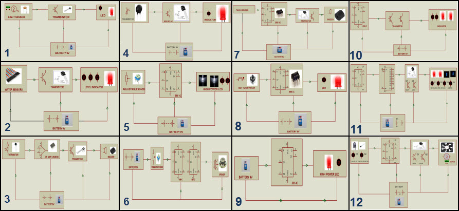
Step1: Fire Alarm Circuit Block Diagram Estimation
The block diagram of fire alarm circuit block diagram can be estimated based on the requirement and application of project.
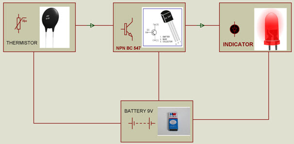
Fire Alarm System Block Diagram
The simple fire alarm system is one of the innovative solderless breadboard projects. This fire alarm project block diagram consists of thermistor, transistor, indicator and battery.
Step2: Gathering Required Components for Fire Alarm Circuit

Electrical & Electronics
Components
Based on the block diagram of fire alarm
system the components required for designing fire alarm circuit can be
estimated. Thus, all the required electrical and electronic components
can be purchased from any online electronics stores (like
www.edgefxkits.com in various types of kits such as a project kit –
individual components, ready-made kit – fully developed kit-plug &
play type and DIY kit – Do It Yourself kit). The electronics components such as thermistor, transistor, indicator, battery, etc., are required components for designing fire alarm circuit.
Step3: Estimating the Fire Alarm Circuit Diagram
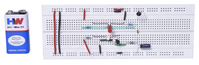
Fire Alarm System Breadboard Project
The components are connected together to
form the fire alarm circuit using connecting wires as shown in the
above figure. Here, a solderless breadboard is used to connect all the
components to form the required fire alarm project circuit. The same set
of components can be used for designing different circuits or to enhance the circuit by connecting a few additional components.
Step4: Connecting & Soldering Circuit

Soldering Procedure
The same circuit after testing output over solderless breadboard can be connected over PCB (printed circuit board) and
soldered to avoid misplacing of the components or disconnection of the
circuit. The soldering of components to form a circuit can be done by
following a few basic soldering techniques. Thus, the circuit can be connected and soldered on PCB according to the tested circuit.
Step5: Fire Alarm Working Principle
The fire alarm working principle is based on thermistor used in the fire alarm circuit.
This fire alarm circuit is used to identify and indicate an increase in
temperature beyond certain value (temperature of an enclosed area).
The increase in temperature is indicated
by turning ON the LED (cooling system can be used to bring the
temperature to its normal value). Thus, if the temperature exceeds a
certain value, then the cooler or load turns ON automatically without
any monitoring system. To actuate the relay instead of LED, operational amplifier along with negative coefficient thermistor can be used.
In this fire alarm mini project circuit,
thermistor is used as a temperature sensor because thermistor is very
economical compared to all other temperature sensors.
But, for applications that require linear response correction is needed
as thermistors exhibit highly nonlinear resistance vs temperature
characteristics. In the above block diagram if the temperature changes
then the input to NPN transistor changes. The output of NPN transistor
is used to turn ON the LED indicator. The accuracy of this fire alarm mini project
can be increased by using a digital temperature sensor instead of
analog. This project can be further enhanced to extinguish fire using
fire fighting robot project.
The fire fighting robot
is used to extinguish fire which can be detected using temperature
sensor. The fire fighting robot consists of a water tank with a pump to
sprinkle water in case of a fire accident.
Are you interested in designing electronics projects?
Do you want to design fire alarm project on your own using our
solderless breadboard project? Feel free to post your comments,
suggestions and ideas in the comments section below.


No comments:
Post a Comment