


An electrical circuit
is a simplified representation of an electric circuit element. This
uses standard symbols for the components in the circuit and does not
show the physical arrangements of the components. Daily life on the
earth is nearly impossible without electricity use. Homes to big
industries we depend on electricity. Electric current flows in a closed
circuit loop. It is a closed loop in which continuous electric current
goes from the supply to the load equipment. When we want to explain a
lighting circuit, it takes more time to draw the all components because,
different people draw various components of the circuit in different
ways and this may take a long time to explain all equipment. It’s better
to learn how to show simple Circuit Projects circuit layouts. Let’s give the drawings for some simple electrical circuits.
Electrical Circuits For Mini Projects For Engineering Students
AC Circuit for Lamp
The lamp requires two wires to glow, one
is the neutral wire and the other one is the live wire. These two wires
are connected from the lamp to the main supply panel. It is advisable
to use red and black color wires for live and neutral wires in an Electrical Circuit Projects,
where red color is used for live wire and black color is used for
neutral wire. A switch is used to control the circuit by switching ON
and OFF.
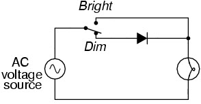
AC Circuit for Lamp
It is provided in the live wire between
the main supply and load. When the switch goes ON electric circuit is
closed and the lamp glows and when the switch is OFF light will
disconnect the power supply to the load. This wiring is placed in a box
called a switch box for better operation. Switch wire and live wire are a
single wire and it is just cut in between to connect the switch.
Battery Charging Circuit
The battery charging is done by means of a rectifier and we know the main function of the rectifier is to convert AC into DC. The rectifier shown in the diagram is the bridge rectifier that has four diodes connected in the form of a bridge.
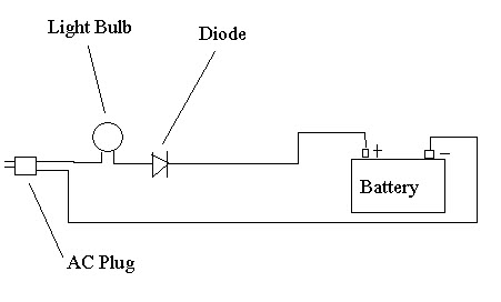
Battery Charging Circuit
We use this in Simple Electrical Circuit
Projects. A resistance is added in the circuit to limit the flow of
current. Supply is given to the rectifier through a step down transformer
that converts the AC supply into DC supply and this flows to the
battery. Generally, this circuit is enclosed in a battery charger unit
or inverter and only the terminals emerge out of the charger unit to be
connected to the battery to charge.
Electric Circuit for Air Conditioning
Air conditioning is a process that
circulates air together with the control of its moisture. The electric
aspect of AC comprises the power equipment for motors and starters
for the compressor and condenser fan equipment. Electrical equipment
includes solenoid valves, pressure switch, together with the safety
cut-out for over current.

Air Conditioning Electric Circuit
The compressor and condenser fans are driven by a simple fixed speed-3 phase AC induction motor
with its own starter and supplied from a distribution board. The
routine electric maintenance and fault finding on the motor and starters
involves cleaning and checking of connections.
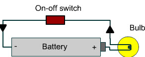
Switch Circuit
Many times in a day, we use switch
buttons, but we usually don’t try to see the connection made inside the
switch operation. The function of the switch is to connect or complete the circuit going to the Load from the supply and move contacts which are normally open.
Switch Circuit
The power supply to the load is through
the switching circuit and therefore the power supply can be cut by
keeping the switch open.
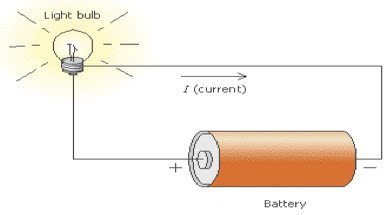
DC Lighting Circuit
For a small LED we use a DC supply,
that has two points they are anode and cathode. The anode is positive
and cathode is negative. A lamp has two terminals one is positive and
the other is negative. The positive terminal of the lamp is connected to
the anode and the negative terminal of the lamp is connected to the
cathode of the battery.
DC Lighting Circuit
When the connection is made the lamp
will glow. Connect a switch in between any one wire that will cut off or
supply DC voltage to the LED bulb.
We discussed about a few simple
electrical circuits, let’s continue a few simple electrical devices.
Also see the circuit functioning and uses of these devices.
Thermocouple Circuit
An EMF is generated when the junctions
formed from two dissimilar homogenous materials are exposed to the
temperature difference. It is called the Seebeck effect. A thermocouple
that consists of two wires.
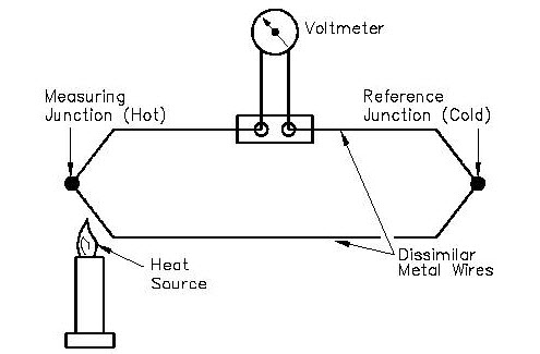
Thermocouple Circuit
The voltmeter will measure the EMF
generated and this can be calibrated to measure the temperature. This
difference between the hot and cold junction will produce an EMF
proportional to it. When the cold junction temperature is kept constant,
then the EMF is proportional to the temperature of the hot junction.
Energy Meter
Energy is the total power consumed over a time interval period. This can be measured by a motor meter or energy meter.
These energy meters are used in all power supply lines to every house
in order to measure the power consumed in both DC and AC circuits. Here
energy is measured in watt-hour or kilowatt hour. In D.C power the meter
may be an ampere hour or a watt-hour meter. An aluminium disc will
rotate continuously when power is consumed.
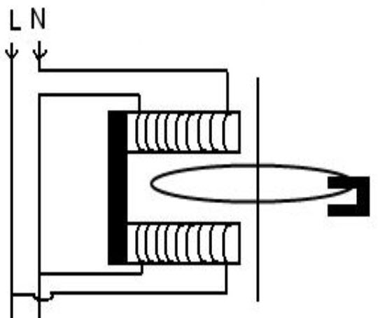
Energy Meter
Speed of rotation will proportional to
the power consumed by the load in watt hour. These will have a pressure
coil and a current coil. The voltage is applied across the pressure
coil. Current flows through the coil and produces a flux which exerts
torque on the disc. The Load current flows through the current coil and
produces another flux which exerts an opposite torque on the aluminium
disc and resultant torque acts on the disc. Results in a rotation on the
disc, which is proportional to the energy utilized and which is
recorded.
Multimeter Circuit
A multimeter is probably one of the most
simple electrical device. Which measures currents, resistance and
voltage. The multimeter is an indispensable instrument and can be used
for measuring DC as well as AC parameters. It is used for checking the continuity of a circuit by ohm meter scale.

Multimeter Circuit
Multimeter consists of a galvanometer
connected in series with a resistance. The Voltage across the circuit
can be measured by connecting the terminals of the multimeter across the
circuit. This is Mainly used to test the continuity of the windings in a
motor.
Therefore, this is all about Simple
electrical Circuits Projects for engineering students, these basic
circuits are designed by using various electrical and electronic
components and these circuits are very helpful to build the electrical projects. We hope that you have got an idea about the electrical circuits.Furthermore, any queries regarding this concept or electronics projects, you can approach us by commenting in the comment section below. Here is a question for you, what is the full form of KVAR?
Photo Credits:
- AC Circuit for Lamp by eng.cam.ac
- Battery Charging Circuit by alpharubicon
- Electric Circuit for Air Conditioning by binderblues
- Switch Circuit by wikispaces
- DC Lighting Circuit by school-for-champions
- Thermocouple Circuit by tpub
- Energy Meter by bhs4
- Multimeter Circuit by physicsnet


No comments:
Post a Comment